Modern technology is expanding the world at a very rapid rate, and its effects easily get felt in our day-to-day activities. Our way of life has altered significantly. Many advanced pieces of equipment have entered the globe thanks to technical advancements that we could not have predicted ten years ago. The Printed Circuit Boards serve as the equipment’s central component and result from engineering technology.
The rigid body that houses different electrical parts is known as the PCB, which is typically green in color. In a procedure known as “PCB Assembly” or PCBA, these components get glued onto the PCBs. Give this article a careful read to learn more about PCB Assembly!
What Is PCBA Or PCB Assembly?
The components are arranged on it to enable the PCB to perform as intended. The PCB’s functionality is what matters most. Even if a tiny SMT resistor does not get installed correctly or a small track gets removed from the PCB, the PCB can still not function. Therefore, the parts must get put together correctly. When parts get integrated, the PCB is called an “assembled PCB” or “PCBA.” This process can be completely done in companies like FS PCBA and ELE PCB Assembly.
PCB Assembly Process:
Adding solder paste to the board, selecting and arranging the components, soldering, inspecting, and testing are some of the processes in the PCB assembly process. All of these procedures must get followed and monitored to ensure that a high-quality objective has been achieved.
Since almost all PCB assembly these days employs surface mount technology, the PCB assembly technique detailed below implies that surface mount components are being used. Let’s read the process:
1. Using A Stencil To Apply Solder Paste
The parts of the PCB board where the parts will fit get first covered with solder paste. On the stainless stencil, solder paste gets used to accomplish this. A mechanical fixture holds the stencil and PCB together while the sprayer applies the solder paste uniformly to all board openings. The applicator evenly distributes the solder paste. Therefore, the appropriate amount of filling must get utilized in the applicator. The paste stays in the desired PCB locations when the applicator gets removed.
The filler metal is a grey hue and gets made of 96.5 percent of tin, 3 percent silver, and 0.5 percent copper. It is also lead-free. When heat is applied, this solder paste melts and solidifies the joint.
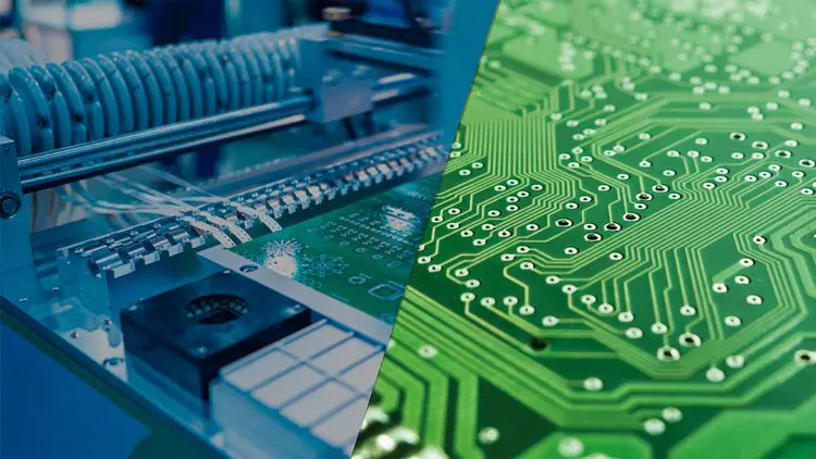
2. Automated Components Placement
The automated insertion of SMT components onto PCB boards is the second step in PCB assembly. Pick and place robots get used to accomplishing this. The automated robots will get a file the architect prepares at the design level.
This file contains the preset X and Y coordinates for every component used on the PCB and shows where each component gets located. Hence, the bot will accurately mount the SMD gadgets on board using this data. Well, the pick-and-place bots will precisely arrange the parts on top of the solder paste after removing them from its vacuum hold.
3. Soldering By Reflow
Reflow soldering is the third stage after the components get placed, and solder paste gets used. The PCBs and the parts get placed on the belt conveyor during the reflow soldering. The PCBs and other components are then moved via this conveyer belt in a large oven with a 260° C temperature. The solder will dissolve at this heat. The parts will then get fixed to the PCB and joints created by the melted solder.
The PCB enters coolers after being subjected to high-temperature treatment. The solder connections are then controlled and solidified by these coolers. As a result, the SMT component and PCB will get permanently joined.
4. Inspection And QC
There is a risk that the components got out of alignment after the reflow soldering because of some mistaken movement in the PCB retaining tray, which could lead to a short circuit or open connection.
It is necessary to identify these defects, and the process of doing so is known as inspection. Both human and automated inspection is possible.
5. Soldering and Fixing THT Components
On many PCBs, through-hole components get frequently seen. These parts are also referred to as Plated through Holes. These parts have leads that can fit through the PCB hole. Copper wires link these holes to other holes. These THT parts are electronically coupled to other holes on the same PCB as the circuit when they are placed and soldered into these holes.
The soldering technique outlined above for SMT components, such as reflow soldering, won’t work on THT components since these PCBs may contain both THT and SMD components in varying amounts.
6. Last Check and Functional Test
The PCB now gets prepared for the inspection process. It is the functionality test, in which the PCB gets supplied with electrical impulses and power at the designated ports and the output gets examined at the designated test points or output connectors. Laboratory tools, including an oscilloscope, a DMM, and a power source, are needed for this test.
This test examines the PCB’s electrical properties, functionality, and compliance with PCB and circuit design specifications for current, voltage, analog, and digital output. According to the company’s standard operating procedures, the PCB gets rejected or trashed if any criteria yield undesirable results. The testing phase is crucial because it decides if the PCBA manufacturing process will be successful or not.
7. Final Cleanup, Completion, And Shipping
It is now time to wipe the undesired leftover flux, finger dust, and oil stains after the PCB was tested and given the all-clear. All forms of dirt can get removed with a high-pressure washer made of stainless steel and deionized water.
However, the deionized water won’t harm the PCB circuit. After washing, compressed air gets used to dry the PCB. Now, the finished PCB gets prepared for packaging and shipping.
Summing Up!
We can conclude that depending on the criteria provided by the client or user; the PCB function can be either sophisticated or basic. Depending on the requirements, PCB sizes vary as well. Both manual and automated methods get used in PCB assembly. The manufacturer inspects the PCB for any flaws or errors that could lead to malfunction before beginning the PCB production and PCB assembly procedure. However, the full description of the PCB assembly process gets provided above to help you understand it better!