In the world of electrical engineering, mastering resistance combination is very important. Think of it as the puzzle-solving skill for designing efficient circuits.
This guide explores series, parallel connections, and the math behind it, empowering students and professionals to tackle real-world electrical challenges confidently.
Resistances can be connected in three ways as follows:
- Series combination
- Parallel combination
- Series-parallel combination.
1. Series Combination of Resistance
If two or more resistances are connected in such a way that there is only one path for the current to flow, it is known as the series combination of resistances.
In a series combination, resistances are connected end-to-end, and the beginning of the first and the end of the last are taken as two supply terminals as shown in the figure.
Current and Voltage in Series Connected Resistances
Current in Series Combination of Resistance
The current passing through each resistance in a series circuit remains the same as there is only one path for the current to flow.
Voltage in Series Combination of Resistance
When current passes through a series circuit there is a drop of voltage in each resistance.
The voltage drops across the resistances are proportional to their individual resistances as the current passing through each of them is the same and is equal to the total current of the circuit.
Therefore, the supply voltage is equal to the sum of all the voltage drops across the resistances.
Therefore,
- Voltage drop across resistance, r1 = v1 = Ir1
- Voltage drop across resistance, r2 = v2 = Ir2
- Voltage drop across resistance, r3 = v3 = Ir3
where I is the current flowing in the series circuit.
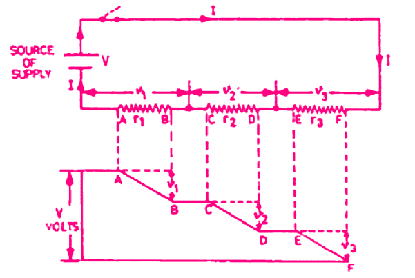
Total Resistance in Series Combination
Consider the three resistances r1, r2, r3 connected in series.
Let the potential difference across all of them be V which causes the same current I amperes to flow in each resistance.
Now the potential difference across each of them will be different.
Let the voltage drops across each resistance be v1, v2, and v3 volt respectively, so that the applied potential difference will be the sum of all the voltages drops, i.e.
V = v1 + v2 + v3
By applying ohm’s law, we have
v1 = Ir1
v2 = Ir2
v3 = Ir3
Putting these values of v1, v2, and v3, in the above equation
V = Ir1 + Ir2 + Ir3
If R is the total resistance of the series circuit, then
V = IR
Putting this value in the above equation, we have
IR = Ir1 + Ir2 + Ir3
or
R = r1 + r2 + r3
Therefore, the total resistance in a series circuit is equal to the sum of the individual resistances.
Uses of Series Combination
We know that in a series circuit there is only one path for the current to flow, but in an open circuit, no current will flow through the circuit. Therefore, series connections are not generally used for house wiring.
These connections are used as given below:
- Where a variable voltage is to be given to the load, a variable resistance is connected in series with the load, e.g. a fan regulator is connected in series with the fan.
- Where many lamps of low voltage are to be operated on the mains supply, they are all connected in series with each other.
- Where a load of low voltage is to be operated on a higher supply voltage, a fixed value of resistance is connected in series with the load.
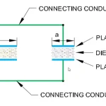
2. Parallel Combination of Resistances
In a parallel combination of resistances, two or more than two resistances are connected in such a way that all the entry ends are joined together at one junction and all the exit ends are connected together at another junction.
These two junctions are taken as terminals for supply. In a parallel combination, there is more than one path for the current to flow.
Current and Voltage in Parallel Connection
Voltage in Parallel Combination
In a parallel circuit, the voltage across each resistance is the same as each resistance is connected across the supply mains.
Current in Parallel Combination
The current flowing through each resistance in a circuit is inversely proportional to the value of individual resistances as the voltage applied at each resistance is the same.
Hence the greater the resistance, the less will be the current flowing through it.
- Current in resistance, r1 = i1 = V/r1
- Current in resistance, r2 = i2 = V/r2
- Current in resistance, r3 = i3 = V/r3
The line current will be equal to the sum of the current flowing through each resistance, i.e. i1 + i2 + i3
If equal values of resistances are connected in parallel, equal currents will flow through each resistance and the total current will be the sum of all currents flowing through the circuit.
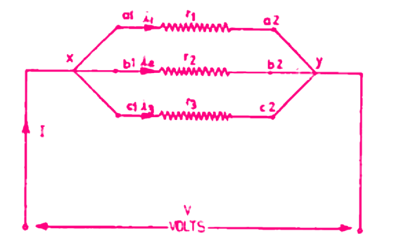
Total Resistances in Parallel Combination Circuit
Now consider three resistances r1, r2, and r3, connected in parallel.
Let the potential difference of V he applied across the two junctions x and y so that the potential is the same across each resistance.
Let the supply current be I A and the current flowing through the individual resistance be i1, i2 and i3 i.e.
I = i1 + i2 + i3
Applying Ohm’s law, we have
i1 = V/r1
i2 = V/r2
i3 = V/r3
Putting these values of i1, i2, and i3 in the above equation,
I = V/r1 + V/r2 + V/r3
If R is total resistance of the parallel combination circuit, then
Total current, I = V/R
R Putting the value in above equation, we have
V/R = V/r1 + V/r2 + V/r3
or
1/R = 1/r1 + 1/r2 + 1/r3
The reciprocal resistance 1/R is also known as conductance represented by G and is measured in mhos (n).
Therefore, in a parallel circuit, the reciprocal of the total resistance is equal to the reciprocal of the sum of the individual resistances.
Use of Parallel Connection
Parallel connections are used in all types of houses and power wiring because in this connection the working voltage of the load is equal to the supply voltage.
Equal Resistances in Parallel
If three resistances each equal to r ohm are connected in parallel, then
1/R = 1/r + 1/r + 1/r = (1 + 1 + 1) / r = 3/r
∴ R = r/3
Total resistance when equal resistances connected in parallel = (Value of one resistance) ÷ (No. of resistances connected in parallel)
It means that the total resistance will be one-third of the resistance of one of them. Hence if n number of equal resistances are connected in parallel, then
Total resistance = 1/n × resistance of one of them.
Unequal Resistances in Parallel
If there are only two resistances connected in parallel, then
1/R = 1/r1 + 1/r2
1/R = ( r2 + r1 ) / r1r2
R = r1r2 / ( r2 + r1 )
Total resistance = (product of two resistances) / (sum of the two resistances)
When there are three resistances connected in parallel, then
1/R = 1/r1 + 1/r2 + 1/r3
1/R = ( r2r3 + r3r1 + r2r1) / r3r1r2
R = r1r2r3 / ( r2r3 + r3r1 + r2r1)
3. Series-Parallel Combination of Resistances
The figure below shows the arrangement of series-parallel combinations of resistances.
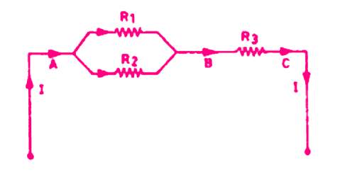
In this circuit, the current divides itself into two branches. More complicated circuits of series-parallel combinations are also called network circuits.
The current and voltage drops of various branches can be more easily calculated with the help of Kirchhoff’s laws.