• Home
  • Courses
  • Machines
    • Transformer
    • AC Motors
      • Induction Motor
      • Synchronous Motor
    • DC Motor
    • DC Generator
  • Power System
    • Circuit Breaker
    • Switchgear
    • Substation
    • Control System
    • Measurement
  • Electronics
  • Blog
  • Contact
    • Contact Us
    • Privacy Policy
Have any question?
[email protected]
RegisterLogin
StudyElectrical.Com
  • Home
  • Courses
  • Machines
    • Transformer
    • AC Motors
      • Induction Motor
      • Synchronous Motor
    • DC Motor
    • DC Generator
  • Power System
    • Circuit Breaker
    • Switchgear
    • Substation
    • Control System
    • Measurement
  • Electronics
  • Blog
  • Contact
    • Contact Us
    • Privacy Policy

Electrical Machines

Parallel Operation of DC Series Generator

  • Categories Electrical Machines, Alternator, DC Generator, Generation, Power System
parallel operation of series dc generator

The interesting thing about the parallel operation of the DC series generator is that DC series generators are not usually employed for the supply of power. Instead, DC series motors are arranged in parallel to operate as DC series generators during Electric Braking. 

Table of Contents

  • Parallel Arrangement of DC Series Generator
  • Parallel Operation of Series Generator
    • Parallel Operation Without Equalizing Bar
    • Parallel Operation With Equalizing Bar
    • Related Articles

Parallel Arrangement of DC Series Generator

The parallel arrangement of DC series generators are described below:

The two DC series motors are disconnected from the supply mains and are connected in parallel to the resistors.

During braking the motors continue to run due to the kinetic energy of train and act as self-excited dc series generators generating emfs.

The kinetic energy is converted into heat and dissipated in the resistors. This is how DC series generators work while operating in parallel.

Parallel Operation of Series Generator

For satisfactory parallel operation of dc series generators, it is necessary to connect the armatures of the two machines through a heavy copper bar, called the equalizing bar.  It is explained below :

Parallel Operation Without Equalizing Bar

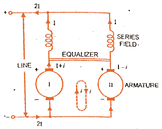
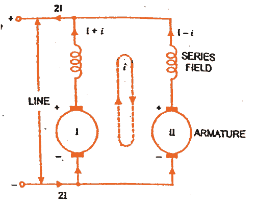
Let two DC machines (I and II) of resistance R (the armature and field resistance), induced EMFs E1 and E2 operate in parallel, as shown in the first figure.
 preview file%2B(1)
When the induced EMFs E1 and E2 are equal they will share the equal load. 

There is a problem when induced EMFs are different in the two machines. When one of the induced emf becomes greater than another induced emf a circulating current will flow.

If E1 becomes slightly greater than E2, then a current i will circulate in the clockwise direction, as shown by dotted lines in the first figure. The magnitude of the circulating current i will be (E1-E2) /R. 

Now total current supplied by machine I will be (I + i) and of machine II (I – i). So the series field current of the machine I increase, also characteristic of a DC series generator is a rising characteristic.

Thus the induced emf of machine I (E1) will rise and induced emf of machine II will fall. Thus the difference of the two induced EMFs E1 am E2 will increase, which will cause a further increase in circulating current.

Thus the effect is cumulative and if there were no fuse or automatic switch in the circuit, the current it machine II will be reversed. This would reverse the direction of induced emf E2 and resultant emf in the circuit would be [E – (- E2)] i.e. (E1 + E2) and circulating current (E1+ E2)/2R. 

Thus the two EMFs will then act in series around a circuit of very low resistance and conditions are virtually those of a short-circuit on the two machines resulting in damage of the machines. We have to avoid this short circuit problem for the parallel operation of DC series generators.

Parallel Operation With Equalizing Bar

Here comes the use of equalizer bars in the parallel operation of DC series generators. 
preview file%2B(2)
The possibility of reversal of either machine can be prevented by preventing the flow of circulating current produced due to inequalities of induced EMFs of the machines through the series field winding. 

This aim can be achieved by connecting a heavy copper bar of negligible resistance across the two machines as shown in the figure.

Now the circulating current does not affect the field winding, but it gets confined to the armature and the equalizing bars. Now if the armature current increases, the terminal voltage drop occurs and the original condition is restored.
Related Articles

  • Dc machine generator and motor construction
    Advantages of Operating DC Generators in Parallel

    In a DC power plant, power is usually supplied from several generators of small ratings…

  • Dc series generator characteristics
    Characteristics of Series Wound DC Generators

    In this post, you will learn the characteristics of a series wound dc generator. This…

  • external-characteristics-of-dc-compound-generator.
    Characteristics of DC Compound Generator

    In a compound generator, both series and shunt excitation are combined as shown in the…

  • DC Shunt Generator Characteristics
    Characteristics of DC Shunt Generator

    In this article, you will learn the characteristics of a dc shunt generator. A shunt…

  • external-characteristic-of-seperately-excited-dc-generator
    Characteristics of Separately Excited DC Generators

    In a separately excited dc generator, the field coils are energized from an independent source. …

  • types of dc generator
    Types of DC Generator - Series, Shunt and Compound

    A DC generator requires MMF to establish flux in its magnetic circuit. The MMF necessary…

  • Share:
author avatar
Electrical Engineer

Previous post

Armature Reaction in DC Generator
September 7, 2014

Next post

Electric Motor Maintenance : Preventive, Predictive and Reactive Maintenance
September 12, 2014

You may also like

percentage_reactance transformer
Percentage Reactance in Power System (Transformer, Generator or Reactor)
16 January, 2023
transformer-winding
Transformer Windings: Types and Design
22 November, 2022
Photo by Sven Daniel on Unsplash
What is CNC Machining? | Definition, Processes, Components & More
3 November, 2022

Leave A Reply Cancel reply

Your email address will not be published. Required fields are marked *

Search Here

From Blog

Type B MCB
Type B Miniature Circuit Breaker ( Type B MCB)
09Apr2020
Electrical Conductivity Meter
What’s The Advantage Of Eddy Current Testing
20Jul2022
Load Curve and Load Duration Curve
Load Duration Curve in Power Station
29Sep2022
working of three phase induction motor
Three Phase Induction Motor: Construction and Working Principle
21Nov2014

Categories

  • Alternator
  • Arduino
  • Basic Electrical
  • Battery
  • Books
  • Cables
  • Capacitor
  • Career
  • Circuit Breaker
  • Control System
  • DC Generator
  • DC Motor
  • Drives
  • Electric Vehicles
  • Electrical Circuits
  • Electrical Machines
  • Electrical Relays
  • Electrical Safety
  • Electronics
  • Embedded System
  • Exams
  • Generation
  • Guest Post
  • HVDC
  • Instrumentation
  • Interview Questions
  • Locomotives
  • Measurement
  • Microcontroller
  • Objective Questions
  • PCB
  • PLC
  • Power System
  • Problems and Solution
  • Projects
  • Resistor
  • Signals and Systems
  • Single Phase Motors
  • Substation
  • Switchgear
  • Synchronous Motor
  • Three Phase Induction Motor
  • Transformer
  • Transmission Line
  • Uncategorized

Copyright © 2021 Study Electrical, Inc.

© StudyElectrical.Com 2021

Login with your site account

Lost your password?

Not a member yet? Register now

Register a new account

Are you a member? Login now