
The open-loop control system and closed-loop control system are the two types of control systems that you will learn in this article with the help of 4 practical examples from your daily life.
Before going to the details, you must understand what is a control system.
What is a Control System?
A control system consists of subsystems and processes (or plants) assembled for the purpose of obtaining the desired output with desired performance, given a specified input.
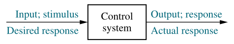
For example, consider an elevator. When the fourth-floor button is pressed on the first floor, the elevator rises to the fourth floor with speed and floor-leveling accuracy designed for passenger comfort. The push of the fourth-floor button is an input that represents our desired output.
Control theory has played a vital role in the advance of engineering and science. The automatic control has become an integral part of modern manufacturing and industrial processes.
Some practical areas where control system are extensively used for are,
- Numerical control of machine tools in manufacturing industries
- Controlling pressure, temperature, humidity
- Controlling viscosity, and flow in the process industry.
When a number of elements or components are connected in a sequence to perform a specific function, the group thus formed is called a system. In a system when the output quantity is controlled by varying the input quantity, the system is called a control system.
The output quantity is called a controlled variable or response and input quantity is called command signal or excitation.
Open Loop Control System
Any physical system which does not automatically correct the variation in its output is called an open-loop system.
or
The control system in which the output quantity has no effect upon the input quantity is called the open-loop control system.
This means that the output is not feedback to the input for correction.
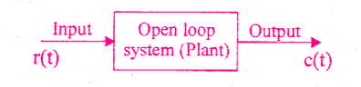
In the open-loop system, the output can be varied by varying the input. But due to external disturbances, the system output may change. When the output changes due to disturbances, it is not followed by changes in input to correct the output.
In open-loop systems, the changes in output are corrected by changing the input manually.
Advantages and Disadvantages
Advantages of open-loop control systems
- The open-loop systems are simple and economical.
- The open-loop systems are easier to construct
- Generally, the open-loop systems are stable.
Disadvantages of open-loop control systems
- The open-loop systems are inaccurate and unreliable.
- The changes in the output due to external disturbances are not corrected automatically.
Closed-Loop Control System
Control systems in which the output has an effect upon the input quantity in order to maintain the desired output value are called closed-loop control systems.
The open-loop control system can be modified as a closed-loop control system by providing feedback.
The provision of feedback automatically corrects the changes in output due to disturbances. Hence the closed-loop system is also called an automatic control system.
The general block diagram of an automatic control system is shown in the figure below.
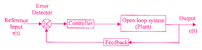
It consists of an error detector, a controller, a plant (open loop system) and feedback path elements.
The reference signal ( or input signal ) corresponds to the desired output. The feedback path elements sample the output and convert it to a signal of the same type as that of the reference signal.
The feedback signal is proportional to the output signal and it is fed to the error detector. The error signal generated by the error detector is the difference between the reference signal and the feedback signal.
The controller modifies and amplifies the error signal to produce better control action. The modified error signal is fed to the plant to correct its output.
Advantages and Disadvantages
Advantages of closed-loop control systems
- The closed-loop systems are accurate.
- The closed-loop systems are accurate even in the presence of non-linearities.
- The sensitivity of the systems may be made small to make the system more stable.
- The closed-loop systems are less affected by noise.
Disadvantages of closed-loop control systems
- The closed-loop systems are complex and costly.
- The feedback in the closed-loop system may lead to an oscillatory response.
- The feedback reduces the overall gain of the system.
- Stability is a major problem in the closed-loop system and more care is needed to design a stable closed-loop system.
4 Examples of Control Systems
Now in this section, you will learn the 4 practical examples of control systems. They are
- Temperature Control System
- Traffic Control System
- Numerical Control System
- Position Control System
Let’s learn each of them in detail how they behave in an open-loop and closed-loop control system.
1. Temperature Control System
The first example is the temperature control system. A Temperature Control System automatically controls the temperature of an object or an area. We commonly use temperature control systems in Air Conditioners, Refrigerators, geysers, electric furnace, etc.
Open-loop Temperature Control System
An electric furnace in the open-loop system is shown in the figure.
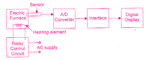
The output in the system is the desired temperature. The temperature of the system is raised by heat generated by the heating element.
The output temperature depends on the time during which the supply to heater remains ON. The ON and OFF of the supply are governed by the time setting of the relay.
The temperature is measured by a sensor, which gives an analog voltage corresponding to the temperature of the furnace. The analog signal is converted to a digital signal by an Analog to Digital converter (A/D converter).
The digital signal is given to the digital display device to display the temperature. In this system, if there is any change in output temperature then the time setting of the relay is not altered automatically.
Closed-loop Temperature Control System
The electric furnace shown in the figure below is a closed-loop system. Tho output of the system is the desired temperature and it depends on the time during which the supply to heater remains ON.
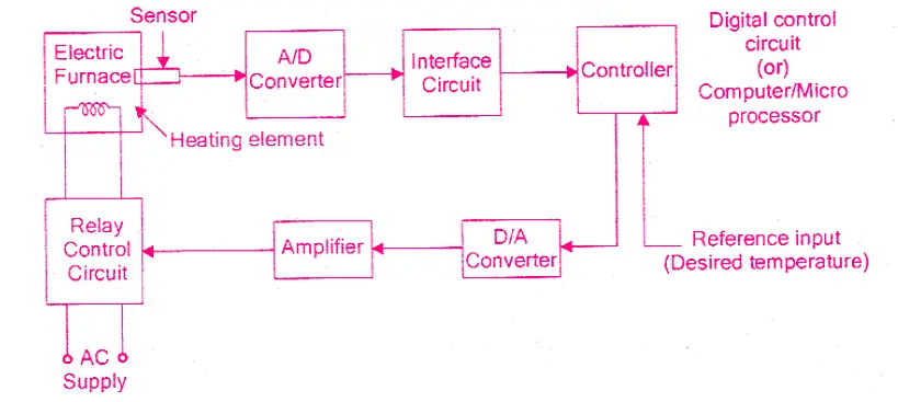
The switching ON and OFF of the relay is controlled by a controller which is a digital system or computer. The desired temperature is input to the system through a keyboard or as a signal corresponding to the desired temperature via ports.
The actual temperature is sensed by the sensor and converted to a digital signal by the A/D converter. The computer reads the actual temperature and compares it with the desired temperature. If it finds any difference then it sends a signal to switch ON or OFF the relay through D/A converter and amplifier. Thus the system automatically corrects any changes in output. Hence it is a closed-loop system.
2. Traffic Control System
The second example is the traffic control system. Traffic control is a critical element in the safe and efficient operation of any transportation system.
Open Loop Traffic Control System
Traffic control by means of traffic signals operated on a time basis constitutes an open-loop control system.
The sequence of control signals is based on a time slot given for each signal. The time slots are decided based on a traffic study. The system will not measure the density of the traffic before giving the signals.
Since the time slot does not change according to traffic density, the system is an open-loop system.
Closed Loop Traffic Control System
The traffic control systems can be made as a closed-loop system if the time slots of the signals are decided based on the density of traffic.
In the closed-loop traffic control system, the density of the traffic is measured on all the sides end the information is fed to a computer. The timings of the control signals are decided by the computer-based on the density of traffic.
Since the closed-loop system dynamically changes the timings, the flow of vehicles will be better than the open-loop system.
3. Numerical Control System
Numerical control is a method of controlling the motion of machine components using numbers.
Open Loop Numerical Control System
Here, the position of the work head tool is controlled by the binary information contained in a disk.
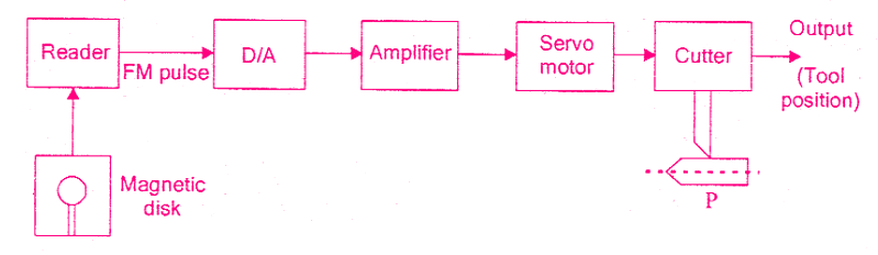
A magnetic disk is prepared in a binary form representing the desired part P (Pis the metal part to be machined). The tool will operate on the desired part P.
To start the system, the disk is fed through the reader to the D/A converter. The D/A convener converts the FM(frequency modulated) output of the reader to an analog signal. It is amplified and fed to servomotor which positions the cutter on the desired part P.
The position of the cutter head is controlled by the angular motion of the servomotor. This is an open-loop system since no feedback path exists between the output and input.
The system positions the tool for a given input command. Any deviation in the desired position is not checked and corrected automatically.
Closed Loop Numerical Control System
A magnetic disk is prepared in a binary form representing the desired part P (P is the metal part to be machined).
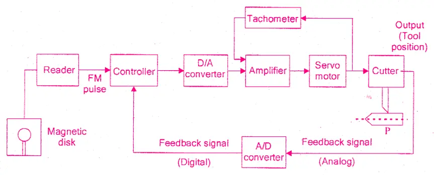
To start the system, the disk is loaded In the reader. The controller compares the frequency modulated input pulse signal with the feedback pulse signal.
The controller is a computer or main processor system. The controller carries out mathematical operations on the difference in the pulse signals and generates an error signal.
The D/A converter converts the controller output pulse (error signal) into an analog signal. The amplified analog signal rotates the servomotor to position the tool on the job.
The position of the cutter head is controlled according to the input of the servomotor. The transducer attached to the cutter head converts the motion into an electrical signal. The analog electrical signal is converted to the digital pulse signal by the A/D converter.
Then this signal is compared with the input pulse signal. If there is any difference between these two, the controller sends a signal to the servomotor to reduce it. Thus the system automatically corrects any deviation in the desired output tool position.
An advantage of numerical control is that complex parts can be produced with uniform tolerances at the maximum milling speed.
4. Position Control System using Servomotor
The position control system shown in the figure is a closed-loop system.
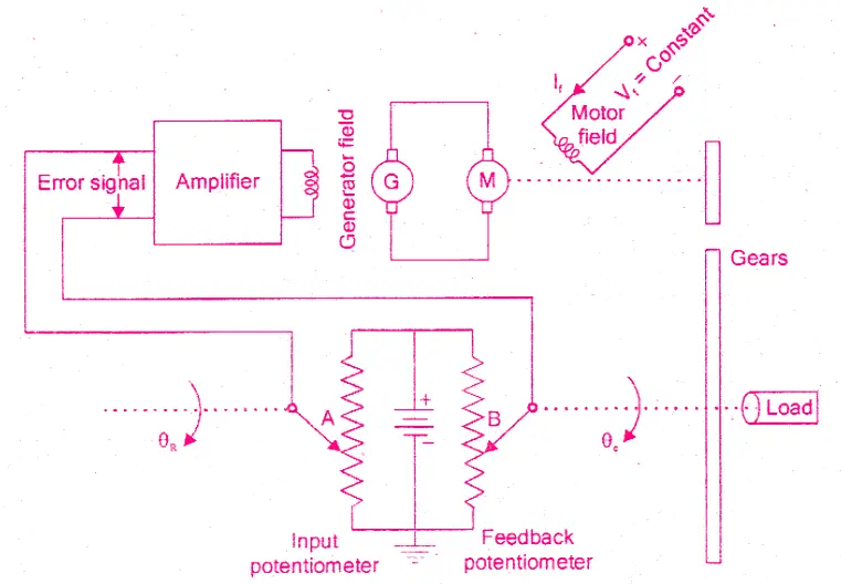
The system consists of a servomotor powered by a generator. The load whose position has to be controlled is connected to the motor shaft through gear wheels.
Potentiometers are used to convert the mechanical motion to electrical signals. The desired load position (θR) is set on the input potentiometer and the actual load position (θS) is fed to feedback potentiometer.
The difference between the two angular positions generates an error signal which is amplified and fed to the generator field circuit. The induced emf of the generator drives the motor. The rotation of the motor stops when the error signal is zero, i.e. when the desired load position is reached.
This type of control system is called servomechanisms. The servo or servomechanisms are feedback control systems in which the output is mechanical position (or time derivatives of position e.g. velocity and acceleration).
Related posts:
 Thermistor Sensor: A Comprehensive Guide
 Miniature cells and Batteries – Silver Oxide, Mercury and Lithium Cells
 Things You Should Know About Electromagnetic Flow Meters
 Introduction to PCB Assembly Process
 Sinusoids and Phasors: Complete Guide
 Digital Multimeter: Working and Application
 Here is Why Your Equipment Needs Solenoid Valves
 FPGA for Beginners: Definition, Landscape and Glossary
 How Can I Find Work in FPGA?
 The Ultimate Guide to Computer Memory