Open Delta Connection is a method of transformer connection used to transform three-phase power using two single-phase transformers. In this article, you will learn how this connection is done and the theory behind this.
The Scott connection is another method used for the same purpose of transforming 3 phase power using two single-phase transformers.
Both of these methods result in slightly unbalanced output voltages under load because of unsymmetrical relations. The unbalance is negligible under usual conditions of operation.
Open Delta Connection (V-V Connection)
If one transformer breaks down in a star-star connected system of 3 single-phase transformers in a substation, three-phase power cannot be supplied until the defective transformer has been replaced or repaired. To eliminate this undesirable condition, single-phase transformers are generally connected in Δ-Δ.
In this case, if one transformer breaks down, it is possible to continue supplying three-phase power with the other two transformers because this arrangement maintains correct voltage and phase relations on the secondary.
However, with two transformers, the capacity of the bank is reduced to 57.7% of what it was with all three transformers in service (i.e., complete Δ-Δ circuit).
How Open Delta Connection Works?
If one transformer is removed in the Δ-Δ connection of three single-phase transformers, the resulting connection becomes open delta or V-V connection.
In complete Δ-Δ connection, the voltage of any one phase is equal and opposite to the sum of the voltages of the other two phases.
Therefore, under no-load conditions, if one transformer is removed, the other two will maintain the same three-line voltages on the secondary side.
Under load conditions, the secondary line voltages will be slightly unbalanced because of the unsymmetrical relation of the impedance drops in the transformers.
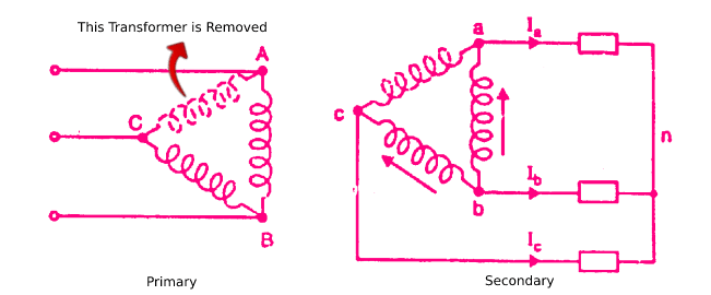
The figure shows an open delta (or V-V) connection; one transformer shown dotted is removed. For simplicity, the load is considered to be star connected.
The figure below shows the phasor diagram for voltages and currents.
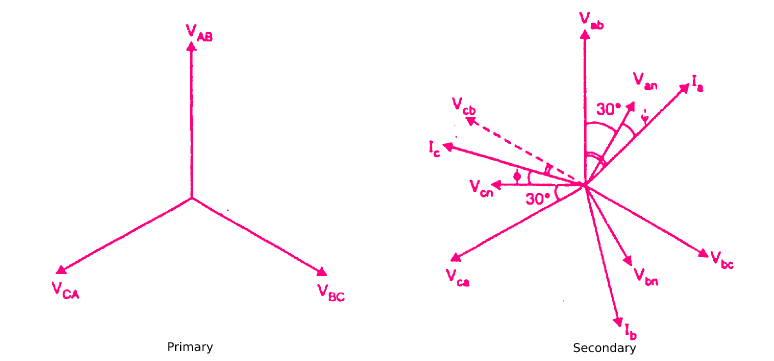
– VAB , VBC, and VCA represent the line-to-line voltages of the primary.
– Vab , Vbc, and Vca represent line-to-line voltages of the secondary.
– Van , Vbn and Vcn represent the phase voltages of the load.
For inductive load, the load currents Ia , Ib and Ic will lag the corresponding voltages Van , Vbn, and Vcn by the load phase angle ϕ.
The transformer windings ab and bc will deliver power given by;
Pab = Vab Ia cos(30° + ϕ)
Pbc = Vcb Ic cos(30° – ϕ)
Let, Vab = Vcb = V, the voltage rating of transformer secondary winding
Ia = Ic = I, current rating of the transformer secondary winding
For resistive load – power factor = 1 i.e. ϕ = 0°
Power delivered to the resistive load by V-V connection is
Pv = Pab + Pbc = VI cos30° + VI cos30° = 2VI cos30°
With all the three transformers connected in delta, the power delivered to the resistive load is
PΔ = 3VI
∴ Pv/PΔ = 2VI cos30°/ 3VI = 2 cos30°/ 3 = 0.577
Hence the power-handling capacity of a open delta (V-V) circuit (without overheating the transformers) is 57.7% of the capacity of a complete Δ-Δ circuit of the same transformers.
In a open delta (V-V) circuit, only 86.6% of the rated capacity of the two transformers is available. This can be readily proved.
Operating Capacity / Available Capacity = 2VI cos30°/2VI = cos30° = √3/2 = 0.866
Example of Open Delta Connection
Let us illustrate the open delta (V-V) connection with a numerical example.
Suppose three identical single-phase transformers, each of capacity 10 kVA, are connected in Δ-Δ. The total rating of the three transformers is 30 kVA.
When one transformer is removed, the system reverts to the open delta (V-V) circuit and can deliver 3-phase power to a 3-phase load.
However, the kVA capacity of the open delta (V-V) circuit is reduced to 30 x 0.577 = 17.3 kVA and not 20 kVA as might be expected.
This reduced capacity can be determined in an alternate way.
The available capacity of the two transformers is 20 kVA. When operating in the open delta (V-V) circuit, only 86.6% of the rated capacity is available i.e. 20 x 0.866 = 17.3 kVA.
Power Factor of Transformers in V-V Circuit
When the open delta circuit is delivering 3-phase power, the power factor of the two transformers is not the same (except at unity p.f.).
Therefore, the voltage regulation of the two transformers will not be the same. If the load power factor angle is f, then,
power factor of transformer 1 = cos (30° – ϕ)
power factor of transformer 2 = cos (30° + ϕ)
1. When load p.f. = 1 i.e. ϕ = 0°
In this case, each transformer will have a power factor of 0.866.
2. When load p.f. = 0.866 i.e. ϕ = 30°
In this case, one transformer will have a power factor of cos (30° – 30°) = 1 and the other of cos (30° + 30°) = 0.5.
3. When load p.f = 0.5 i.e. ϕ = 60°
In this case, one transformer will have a power factor of cos (30° – 60°) = 0.866 and the other of cos (30° + 60°) = 0.
Thus at a load power factor of 0.5, one transformer delivers all the power at 0.866 power factor and the other (although still necessary to be in the circuit) delivers no power at all.
Applications of Open Delta or Open Delta (V-V) Connection
The open delta circuit has a number of features that are advantageous. A few applications are given below by way of illustration:
- The circuit can be employed in an emergency situation when one transformer in a complete Δ-Δ circuit must be removed for repair and continuity of service is required.
- Upon failure of the primary or secondary of one transformer of a complete Δ-Δ circuit, the system can be operated as an open delta (V-V) circuit and can deliver 3-phase power (with reduced capacity) to a 3-phase load.
- A circuit is sometimes installed as an open delta (V-V) circuit with the understanding that its capacity may be increased by adding one more transformer to form a complete Δ-Δ circuit. As shown earlier,
Pv/PΔ = 1/√3 = 0.577
PΔ = √3 Pv
Thus if a V-V circuit is changed to complete Δ-Δ circuit, the capacity is increased by a factor of √3.