Please go through the construction of dc generator before reading this article about different types of dc generator.
A DC generator requires MMF to establish flux in its magnetic circuit. The MMF necessary to establish flux in the magnetic circuit of a dc generator is obtained by field excitation.
When a DC voltage is applied to the field windings of a DC generator, current flows through the windings and sets up a steady magnetic field. This is called field excitation.
Field excitation can be obtained by the following means
- Permanent magnets
- Field coils excited from some external source and
- Field coils excited by the generator itself.
The excitation voltage can be produced by the generator itself or it can be supplied by an outside source, such as a battery.
If the flux is established using permanent magnets, then this type of dc generator is called Permanent magnet dc generator.
If the flux is obtained by exciting field coils from some external source, that type of dc generator is called Separately excited dc generator.
If field coils are excited by the generator itself to establish the required flux, then such type of dc generators are called Self-excited dc generators.
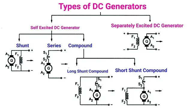
Generators are generally classified according to these methods of field excitation. On this basis, different types of dc generator are divided into the following three classes:
- Permanent magnet dc generators
- Separately excited dc generators
- Self-excited dc generators
- Series Wound dc generator
- Shunt Wound dc generator
- Compound Wound dc generator
In permanent magnet dc machines, a permanent magnet is used to establish flux in the magnetic circuit.
These generators are not found in industrial applications because of the low power generated from it. Such generators are employed only in small sizes like dynamos in motorcycles.
The behavior of a dc generator on load depends upon the method of field excitation adopted.
Separately Excited D.C. Generators
The figure shows the connections of a separately excited generator. The voltage output depends upon the speed of rotation of armature and the field current (Eg = φZNP/60 A). The greater the speed and field current, the greater is the generated e.m.f.
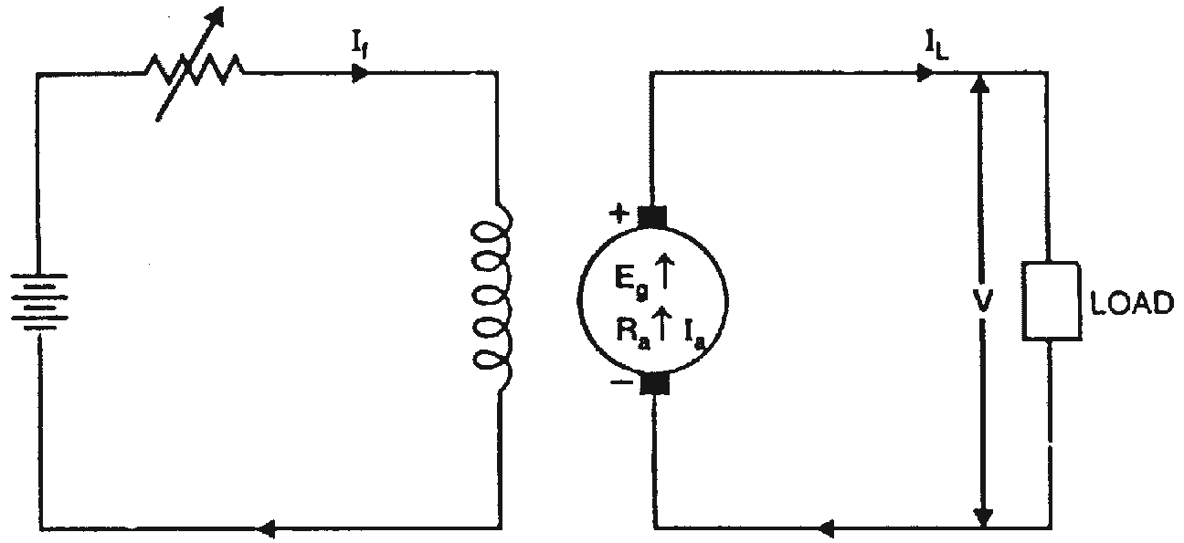
Armature current, Ia = IL
Terminal voltage, V = Eg – IaRa
Electric power developed = EgIa
Power delivered to load = EgIa – I R = I E – I R = VIa
Self-Excited D.C. Generators
A d.c. generator whose field magnet winding is supplied current from the output of the generator itself is called a self-excited generator.
A generator that supplies its own field excitation is called a self-excited generator. Self-excitation is possible only if the field pole pieces have retained a slight amount of permanent magnetism, called residual magnetism.
When the generator starts rotating, the weak residual magnetism causes a small voltage to be generated in the armature. This small voltage applied to the field coils causes a small field current.
Although small, this field current strengthens the magnetic field and allows the armature to generate a higher voltage. The higher voltage increases the field strength, and so on. This process continues until the output voltage reaches the rated output of the generator.
There are three types of self-excited dc generator depending upon the manner in which the field winding is connected to the armature, namely;
- Series generator
- Shunt generator
- Compound generator
1. DC Series Generator
The figure shows the connections of a series-wound generator. Since the field winding carries the whole of load current, it has a few turns of thick wire having low resistance.
Series generators are rarely used except for special purposes e.g., as boosters.

A series-wound generator uses very low resistance field coils, which consist of a few turns of large diameter wire. The voltage output increases as the load circuit start drawing more current.
Under low-load current conditions, the current that flows in the load and through the generator is small. Since small current means that a small magnetic field is set up by the field poles, only a small voltage is induced in the armature.
If the resistance of the load decreases, the load current increases. Under this condition, more current flows through the field. This increases the magnetic field and increases the output voltage.
A series-wound DC generator characteristic shows that the output voltage varies with load current. This is undesirable in most applications. For this reason, this type of generator is rarely used in everyday practice.
2. DC Shunt Generator
In a shunt generator, the field winding is connected in parallel with the armature winding so that the terminal voltage of the generator is applied across it.
The shunt field winding has many turns of fine wire having high resistance. Therefore, only a part of armature current flows through shunt field winding and the rest flows through the load. Also, read the characteristics of a shunt generator.
The figure below shows the connections of a shunt-wound generator.

Current in the field windings of a shunt-wound generator is independent of the load current (currents in parallel branches are independent of each other). Since field current, and therefore field strength, is not affected by load current, the output voltage remains more nearly constant than does the output voltage of the series-wound generator.
In actual use, the output voltage in a DC shunt-wound generator varies inversely as load current varies. The output voltage decreases as load current increases because of the voltage drop across the armature resistance increases (E = IR).
In a series-wound generator, the output voltage varies directly with load current. In the shunt-wound generator, the output voltage varies inversely with load current.
A combination of the two types can overcome the disadvantages of both. This combination of windings is called the compound wound DC generator.
3. DC Compound Generator
In the compound-wound generator when load current increases, the armature voltage decreases just as in the shunt-wound generator. This causes the voltage applied to the shunt-field winding to decrease, which results in a decrease in the magnetic field.
This same increase in load current, since it flows through the series winding, causes an increase in the magnetic field produced by that winding.
By proportioning the two fields so that the decrease in the shunt field is just compensated by the increase in the series field, the output voltage remains constant.
As you can see in compound wound generator characteristics, by proportioning the effects of the two fields (series and shunt), a compound wound generator provides a constant output voltage under varying load conditions.
- Short Shunt Compound DC Generator
- Long Shunt Compound DC Generator

(i) Short Shunt Compound DC Generator (ii) Long Shunt Compound DC Generator
Short Shunt compound dc generator is in which only shunt field winding is in parallel with the armature winding.
Long Shunt compound dc generator is in which shunt field winding is in parallel with both series field and armature winding.
3.1. Long shunt Compound Generator
3.2 Short Shunt Compound Generator
In a compound generator, the major portion of excitation is usually supplied by the shunt field. The shunt field is slightly weaker and the series field is considerably weaker than those of the corresponding machine in which the entire excitation is produced by a single shunt or a single series winding.
Compound wound generators are of two types, known as cumulative wound and differential wound generators.
In cumulative wound generators the series field assists the shunt field, whereas, in differential wound generators, series field opposes the shunt field.
Comments are closed.