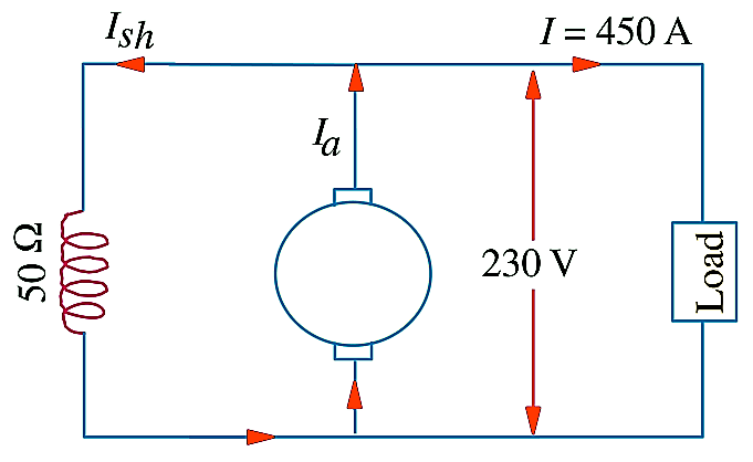
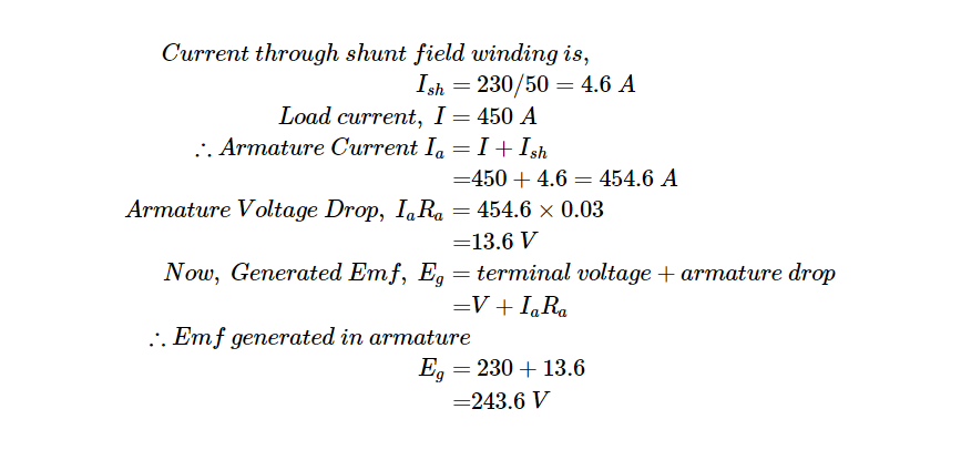
• Home
  • Courses
  • Machines
    • Transformer
    • AC Motors
      • Induction Motor
      • Synchronous Motor
    • DC Motor
    • DC Generator
  • Power System
    • Circuit Breaker
    • Switchgear
    • Substation
    • Control System
    • Measurement
  • Electronics
  • Blog
  • Contact
    • Contact Us
    • Privacy Policy
Have any question?
[email protected]
Login
StudyElectrical.Com
  • Home
  • Courses
  • Machines
    • Transformer
    • AC Motors
      • Induction Motor
      • Synchronous Motor
    • DC Motor
    • DC Generator
  • Power System
    • Circuit Breaker
    • Switchgear
    • Substation
    • Control System
    • Measurement
  • Electronics
  • Blog
  • Contact
    • Contact Us
    • Privacy Policy

    DC Generator

    6 DC Generator Problems with Solution – Types of DC Generator

    • Categories DC Generator, DC Generator Solved Problems, Electrical Machines, Exams, Interview Questions, Objective Questions, Problems and Solution
    DC generator problem 1

    This set of DC Generator Problems with Solution focuses on problems based on Types of DC Generator.

    Table of Contents

    • DC Generator Problem 1
    • DC Generator Problem 2
    • DC Generator Problem 3
    • DC Generator Problem 4
    • DC Generator Problem 5
    • DC Generator Problem 6
    • Related Articles

    DC Generator Problem 1

    A shunt generator delivers 450 A at 230 V and the resistance of the shunt field and armature are 50 Ω and 0.03 Ω respectively. Calculate the generated EMF?

    DC Generator Problem 1 Solution:

    The Generator Circuit is as shown in the figure,
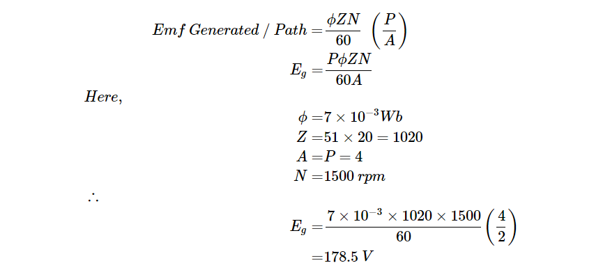
    DC Shunt Generator
    DC Shunt Generator

    Current through shunt field winding is,
    $$
    \begin{aligned}
    I_{\text {sh }} &=230 / 50=4.6 \mathrm{~A} \\
    \text { Load current, } I &=450 \mathrm{~A} \\
    \therefore \text { Armature Current } I_{a} &=I+I_{\text {sh }} \\
    &=450+4.6=454.6 \mathrm{~A} \\
    \text { Armature Voltage Drop, } I_{a} R_{a} &=454.6 \times 0.03 \\
    &=13.6 \mathrm{~V} \\
    \text { Now, Generated Emf, } E_{g} &=\text { terminal voltage }+\text { armature drop } \\
    &=V+I_{a} R_{a} \\
    \therefore \text { Emf generated in armature } & \\
    E_{g} &=230+13.6 \\
    &=243.6 \mathrm{~V}
    \end{aligned}
    $$

    DC Generator Problem 2

    A four pole generator having wave-wound armature winding has 51 slots, each slot containing 20 conductors. What will be the voltage generated in the machine when driven at 1500 rpm assuming the flux per pole to be 7.0 mWb ?

    DC Generator Problem 2 Solution:

    For a simplex wave wound generator,

    The formula to calculate the generated voltage of a DC generator is:

    E = (P * Z * N * Φ) / (60 * A)

    where:
    E = generated voltage in volts (V)
    P = number of poles
    Z = total number of armature conductors
    N = speed of the generator in revolutions per minute (RPM)
    Φ = flux per pole in webers (Wb)
    A = number of parallel paths in the armature winding

    In this case, we have:
    P = 4 (four poles)
    Z = 51 slots x 20 conductors/slot = 1020 armature conductors
    N = 1500 RPM
    Φ = 7.0 mWb = 7.0 x 10⁻³ Wb
    A = 2 (wave-wound armature winding)

    Substituting these values into the formula, we get:

    E = (4 * 1020 * 1500 * 7.0 x 10^-3) / (60 * 2)
    E = 357 V

    Therefore, the generated voltage of the four pole generator with a wave-wound armature winding, 51 slots each containing 20 conductors, and a flux per pole of 7.0 mWb when driven at 1500 RPM is 357 volts.

    DC Generator Problem 3

    A long-shunt compound generator delivers a load current of 50 A at 500 V and has armature, series field and shunt field resistances of 0.05 Ω, 0.03 Ω and 250 Ω respectively. Calculate the generated voltage and the armature current. Allow 1 V per brush for contact drop.

    DC Generator Problem 3 Solution:

    Generator circuit is shown in figure

    dc generator problem 3
    Long Shunt Compound DC Generator

    Current through shunt field winding, Ish= 500/250 = 2 A

    Current through armature and series winding = 50 + 2 = 52 A

    Voltage drop on series field winding = 52×0.03 = 1.56 V

    Armature voltage drop, IaRa = 52×0.05 = 2.6 V

    Drop at brushes = 2×1 = 2 V

    Now Emf generated in armature, Eg = V + IaRa+ series drop + brush drop
    = 500 + 2.6 + 1.56 + 2 = 506.16 V

    DC Generator Problem 4

    A short-shunt compound generator delivers a load current of 30 A at 220 V, and has armature, series-field and shunt-field resistances of 0.05 Ω, 0.30 Ω and 200 Ω respectively. Calculate the induced emf and the armature current. Allow 1.0 V per brush for contact drop.

    DC Generator Problem 4 Solution:

    A Short Shunt Compound Wound Generator is a type of dc generator in which the shunt field winding is connected in parallel with the armature winding only.

    The circuit diagram of short-shunt compound generator mentioned in the problem is given below

    short shunt dc compound generator problem 4
    Short Shunt Compound DC Generator

    Voltage drop in series winding = 30 × 0.3 = 9 V

    Voltage across shunt winding = 220 + 9 = 229 V

    Ish = 229/200 = 1.145 A

    Ia = 30 + 1.145 = 31.145 A

    IaRa = 31.145 × 0.05 = 1.56 V

    Brush drop = 2 × 1 = 2 V

    Eg = V + series drop + brush drop + IaRa
    = 220 + 9 + 2 + 1.56 = 232.56 V

    DC Generator Problem 5

    In a long-shunt compound generator, the terminal voltage is 230 V when generator delivers 150 A. Determine
    (i) induced emf
    (ii) total power generated
    (iii) distribution of this power.
    Given that shunt field, series field, divertor and armature resistance are 92 Ω, 0.015 Ω, 0.03 Ω and 0.032 Ω respectively.

    DC Generator Problem5 Solution:

    Ish = 230/92 = 2.5 A
    Ia = 150 + 2.5 = 152.5 A

    dc generator problem 5
    Long Shunt DC compound Generator with divertor resistances

    Since series field resistance and divertor resistances are in parallel their combined resistance is = 0.03 × 0.015/0.045 = 0.01 Ω

    Total armature circuit resistance is = 0.032 + 0.01 = 0.042 Ω
    Voltage drop = 152.5 × 0.042 = 6.4 V

    (i) Voltage generated by armature, Eg = 230 + 6.4 = 236.4 V

    (ii) Total power generated in armature, EgIa = 236.4 × 152.5 = 36,051 W

    (iii) Power distribution

    Power lost in armature IaRa = 152.52 × 0.032 = 744 W
    Power lost in series field and divertor = 152.52 × 0.01 = 232 W
    Power dissipated in shunt winding = VIsh = 230 × 0.01 = 575 W
    Power delivered to load = 230 × 150 = 34500 W

    Total = 36051 W

    DC Generator Problem 6

    The following information is given for a 300-kW, 600-V, long-shunt compound generator : Shunt field resistance = 75 Ω, armature resistance including brush resistance = 0.03 Ω, commutating field winding resistance = 0.011 Ω, series field resistance = 0.012 Ω, divertor resistance = 0.036 Ω. When the machine is delivering full load, calculate the voltage and power generated by the armature

    DC Generator Problem 6 Solution:

    Power output = 300,000 W
    Output current = 300,000/600 = 500 A

    Long shunt DC Generator
    Long Shunt DC compound Generator with divertor resistance

    Ish = 600/75 = 8 A,
    Ia= 500 + 8 = 508 A

    Since the series field resistance and divertor resistance are in parallel, their combined resistance is = (0.012 × 0.036) / 0.048 = 0.009 Ω

    Total armature circuit resistance = 0.03 – 0.011 + 0.009 = 0.05 Ω

    Voltage drop = 508 × 0.05 = 25.4 V

    Voltage generated by armature = 600 + 25.4 = 625.4 V

    Power generated = 625.4 × 508 = 317,700 W = 317.7 kW

    More: DC Generator Problems and Solution: EMF Equation of DC Generator

    Related Articles

    • adcmotor
      Losses in DC Machine ( DC Generator and Motor )

      The losses in a dc machine (generator or motor) may be divided into three classes viz …

    • parallel operation of series dc generator
      Parallel Operation of DC Series Generator

      The interesting thing about the parallel operation of the DC series generator is that DC…

    • dc generator open circuit characteristics
      DC Generator Characteristics

      DC generator characteristics are the relations between excitation, terminal voltage and load exhibited graphically by means…

    • external-characteristics-of-dc-compound-generator.
      Characteristics of DC Compound Generator

      In a compound generator, both series and shunt excitation are combined as shown in the…

    • DC Shunt Generator Characteristics
      Characteristics of DC Shunt Generator

      In this article, you will learn the characteristics of a dc shunt generator. A shunt…

    • Share:
    author avatar
    Electrical Engineer

    Previous post

    Difference between Dielectric Testing & Insulation Resistance Measurement
    January 18, 2018

    Next post

    Voltage and Power Equations of DC Motor | Condition of Maximum Power
    January 19, 2018

    You may also like

    gadgets for electrical engineering students
    4 Must-Have Gadgets for Electrical Engineering Students: Boost Your Learning and Productivity
    28 February, 2023
    DC Machines Construction MCQ
    DC Machines Construction MCQ Objective Question Quiz with Answer
    24 February, 2023
    transformer-winding
    Transformer Windings: Types and Design
    22 November, 2022

      10 Comments

    1. Mohammed Uzair Dawalji
      January 11, 2019
      Reply

      Excellent

      • SATYAM KUMAR CHAUDHARY
        March 16, 2019
        Reply

        How you say that excellent
        Whenever totally are wrong process

    2. Satyam Kumar
      March 16, 2019
      Reply

      In dc generator wave wound:- Number of poles is not is equal to number of parallel path.
      Always A=2
      Or,
      In lap wound A=mP. Where,
      (A=no. of parallel path)
      (m=no. of winding)
      (P=no. of poles)
      I think it may be right…..

      • Andy Yeboah
        September 10, 2019
        Reply

        Nice explanation.

    3. ASRAR HUSSAIN BHAT
      April 29, 2019
      Reply

      Deduce the internal characteristics from the external characteristics and estimate the full load voltage drop due to armature reaction
      reply,
      please

      • Tesla Edison
        Tesla Edison
        April 24, 2020
        Reply

        https://studyelectrical.com/2014/08/characteristics-of-shunt-generator.html

        • Sand
          February 15, 2022
          Reply

          In second question u should take A=2 not 4 please make sure that

    4. rishabh sisodiya
      January 26, 2020
      Reply

      357 volts is the correct ans.
      A=2 in wave wound dc generator

    5. Yusuf isah
      September 15, 2021
      Reply

      I like so much

    Leave A Reply Cancel reply

    Your email address will not be published. Required fields are marked *

    Search Here

    From Blog

    Transformer Percentage Impedance Testing
    How to Test Percentage Impedance of Transformer?
    02Aug2019
    Tulip contacts of Vacuum Circuit Breaker
    Basic Types of Switchgear Components
    08Sep2015
    Silver oxide minature cell battery
    Miniature cells and Batteries – Silver Oxide, Mercury and Lithium Cells
    06Nov2019
    assignment
    Basic Tips for Students to Write an Essay
    13Sep2021

    Categories

    • Alternator
    • Arduino
    • Basic Electrical
    • Battery
    • Books
    • Cables
    • Capacitor
    • Career
    • Circuit Breaker
    • Control System
    • DC Generator
    • DC Generator MCQ
    • DC Generator Solved Problems
    • DC Motor
    • DC Motor MCQ
    • Drives
    • Electric Vehicles
    • Electrical Circuits
    • Electrical Machines
    • Electrical Relays
    • Electrical Safety
    • Electronics
    • Embedded System
    • Exams
    • Generation
    • Guest Post
    • HVDC
    • Instrumentation
    • Interview Questions
    • Locomotives
    • MCQ
    • Measurement
    • Microcontroller
    • Objective Questions
    • PCB
    • PLC
    • Power System
    • Problems and Solution
    • Projects
    • Resistor
    • Signals and Systems
    • Single Phase Motors
    • Substation
    • Switchgear
    • Synchronous Motor
    • Three Phase Induction Motor
    • Transformer
    • Transmission Line
    • Uncategorized

    Copyright © 2021 Study Electrical, Inc.

    © StudyElectrical.Com 2021

    Login with your site account

    Lost your password?