• Home
  • Courses
  • Machines
    • Transformer
    • AC Motors
      • Induction Motor
      • Synchronous Motor
    • DC Motor
    • DC Generator
  • Power System
    • Circuit Breaker
    • Switchgear
    • Substation
    • Control System
    • Measurement
  • Electronics
  • Books
  • Blog
  • Forums
  • Contact
    • Contact Us
    • About
    • Privacy Policy
RegisterLogin
StudyElectrical.ComStudyElectrical.Com
  • Home
  • Courses
  • Machines
    • Transformer
    • AC Motors
      • Induction Motor
      • Synchronous Motor
    • DC Motor
    • DC Generator
  • Power System
    • Circuit Breaker
    • Switchgear
    • Substation
    • Control System
    • Measurement
  • Electronics
  • Books
  • Blog
  • Forums
  • Contact
    • Contact Us
    • About
    • Privacy Policy

Substation

  • Home
  • Blog
  • Substation
  • Substation Earthing System ( Grounding System ) – Earthing Mat

Substation Earthing System ( Grounding System ) – Earthing Mat

  • Categories Substation, Circuit Breaker, Electrical Relays, Power System, Switchgear, Transformer
Substation Earth Mat earth grid
The substation earthing system comprises of a grid (earth mat) formed by a horizontal buried conductors. 

Read about design of substation earthing system here.

The grounding system in substation is very important. The functions of grounding systems or earth mat in include:
  • Ensure safety to personnel in substations against electrical shocks.
  • Provide the ground connection for connecting the neutrals of stat connected transformer winding to earth ( neutral earthing ).
  • Discharge the overvoltages from overhead ground wires or the lightning masts to earth. To provide ground path for surge arresters.
  • Provide a path for discharging the charge between phase and ground by means of earthing switches.
  • To provide earth connections to structures and other non-current carrying metallic objects in the sub-station (equipment earthing).
In addition to such a grid below ground level, earthing spikes (electrodes) are driven into the ground. They are connected electrically to the earth grid, equipment bodies, structures, neutrals, etc. All these are connected to the station earthing system by earthing strips. 
 
If the switchyards have a soil of low resistivity, earth resistance of the earthing system would be low. If the soil resistivity is high, the mesh rods are laid at closer spacing. More electrodes are inserted in the ground.
WP 20140315 10 43 58 Pro
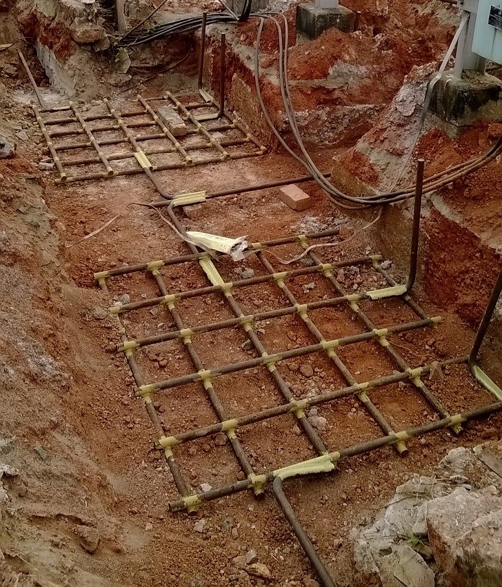
Earth Mat in 110kV side of a  220/110 kV Substation 
The fence, equipment body, tanks, support, structures, towers, structural steelworks, water pipes, etc. should be earthed. 

Earth Resistance Value

The value of earth resistance of the ground system determines the voltage rise of the various earthed points during the earth fault. 

If earth fault current is I, earth resistance is R, the voltage rise under short circuit condition would be V= IR. 

The permissible potential rise and the maximum possible earth fault current set a limit on the maximum value of earth resistance. 

To achieve earth resistance within specified limits, enough number of earth spikes and sufficient surface area of the earth grid and closer ground mesh rods are necessary.

The touch potential and earth potential in the switchyard under any earth fault condition should be within safe limits.

Substation Earthing System Design

  • Share:
author avatar

Previous post

Losses in DC Machine ( DC Generator and Motor )

Next post

Objective Questions on Electric Traction - 1

    1 Comment

  1. seakpi
    May 30, 2019
    Reply

    Many thanks for this specific info on Earthing mat in substations. I was basically researching all Google in order to uncover it!

Leave A Reply Cancel reply

Your email address will not be published. Required fields are marked *

Login with your site account

Connect with

FacebookGoogleLinkedIn

logo


Lost your password?

Not a member yet? Register now

Recent Articles

  • The 6 Flow Meter Types that Your Business Needs to Know About
  • Going Beyond Theory And Books: High-performance Liquid Chromatography
  • How to Select an Electronic Contract Manufacturing Partner
  • 7 FE Electrical and Computer Practice Problems with Solutions
  • Sinusoids and Phasors
For Advertisements Contact
[email protected]

Copyright © 2020 Study Electrical, Inc.

© StudyElectrical.Com 2020

Connect with

Login with Facebook Login with Google Login with LinkedIn

logo

Login with your site account

Connect with

FacebookGoogleLinkedIn

logo


Lost your password?

Not a member yet? Register now

Register a new account

Connect with

FacebookGoogleLinkedIn

logo


Are you a member? Login now