• Home
  • Courses
  • Machines
    • Transformer
    • AC Motors
      • Induction Motor
      • Synchronous Motor
    • DC Motor
    • DC Generator
  • Power System
    • Circuit Breaker
    • Switchgear
    • Substation
    • Control System
    • Measurement
  • Electronics
  • Blog
  • Contact
    • Contact Us
    • Privacy Policy
Have any question?
[email protected]
RegisterLogin
StudyElectrical.Com
  • Home
  • Courses
  • Machines
    • Transformer
    • AC Motors
      • Induction Motor
      • Synchronous Motor
    • DC Motor
    • DC Generator
  • Power System
    • Circuit Breaker
    • Switchgear
    • Substation
    • Control System
    • Measurement
  • Electronics
  • Blog
  • Contact
    • Contact Us
    • Privacy Policy

Power System

Neutral Grounding (Earthing) and Equipment Grounding

  • Categories Power System
Neutral Grounding (Earthing) and Equipment Grounding

Neutral%2BGrounding%2B%2528Earthing%2529%2Band%2BEquipment%2BGrounding
The term Grounding or Earthing refers to the connecting of a conductor to earth. The neutral points of generator and transformer are deliberately connected to the earth.

In 3 phase a.c. systems the earthing is provided at each voltage level. 

If a neutral point is not available, a special Earthing Transformer is installed to obtain the neutral point for the purpose of earthing. 

Neutral points of star connected potential transformers and current transformers are earthed. The neutral earthing has several advantages.

Advantages of Neutral Grounding

The neutral earthing has several advantages.

  • Freedom from persistent arcing grounds. The capacitance between the line and earth gets charged from supply voltage. During the flash-over the capacitance get discharged to the earth. The supply voltage charges it again. Such alternate charging and discharging produces repeated arcs called Arcing Grounds. The neutral grounding eliminates the problem of ‘arcing grounds’. 
  • The neutral grounding stabilizes the neutral point. The voltages of healthy phases with respect to neutral are stabilized by neutral earthing. 
  • The neutral earthing is useful in discharging over-voltages due to lightning to the earth.
  • Simplified design of earth fault protection. 
  • The grounded systems require relatively lower insulation levels as compared with u. grounded systems. 

The modern power systems are 3 phase a.c systems with grounded neutrals.

Equipment Grounding

The Equipment Grounding refers to the grounding of non-current carrying metal parts earth. It is used for safety of personnel. 

If a metal part is grounded, its voltage with respect earth does not rise to a dangerously high value and the danger of a severe shock to personnel avoided. 
Related Articles

  • Rectifier Transformers
    Rectifier Transformer - Working Principle and Application

    What is the Rectifier Transformer? Rectifier transformers are different from normal power and distribution transformers…

  • Why 2BCT 2Bsecondary 2Bshould 2Bnot 2Bopen
    Why Current Transformer (CT) Seconday Should not be Open ?

    Amazed why secondary of current transformer should not be open? If it is left open…

  • Construction of High Voltage Current Transformer
    Basic Types of Current Transformers

    Current Transformers (CT’s) are instrument transformers that are used to supply a reduced value of…

  • substation earthing
    Substation Earthing System Design

    We have already given an introduction to substation earthing system in an article published earlier.…

  • Substation Earth Mat earth grid
    Substation Earthing System ( Grounding System ) - Earthing Mat

    The substation earthing system comprises of a grid (earth mat) formed by a horizontal buried conductors. …

  • GFCI Wiring
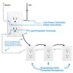
    Why Neutral Grounding or Neutral Earthing is Essential?

    In the power system, grounding or earthing means connecting the frame of electrical equipment (non-current…

  • Share:
author avatar
Electrical Engineer

Previous post

Video : How Does a Tesla Electric Car Work?
February 14, 2018

Next post

Overcurrent Relays for Transmission Line Protection
February 16, 2018

You may also like

percentage_reactance transformer
Percentage Reactance in Power System (Transformer, Generator or Reactor)
16 January, 2023
Load Curve and Load Duration Curve
Load Duration Curve in Power Station
29 September, 2022
Double end break disconnect switch
Disconnect Switches (Isolator) in Substation: Types, Design and Working
1 September, 2022

Leave A Reply Cancel reply

Your email address will not be published. Required fields are marked *

Search Here

From Blog

Build a simple dc motor at home
How to Make a DC Motor at Home?
13Sep2016
Build a simple dc motor at home
Series and Parallel Circuits – A Water Analogy
15Nov2015
Teach Yourself Electricity and Electronics
05Feb2020
Three Phase Transformer
Three-Phase Transformer – Basics and Connection Methods
22Nov2019

Categories

  • Alternator
  • Arduino
  • Basic Electrical
  • Battery
  • Books
  • Cables
  • Capacitor
  • Career
  • Circuit Breaker
  • Control System
  • DC Generator
  • DC Motor
  • Drives
  • Electric Vehicles
  • Electrical Circuits
  • Electrical Machines
  • Electrical Relays
  • Electrical Safety
  • Electronics
  • Embedded System
  • Exams
  • Generation
  • Guest Post
  • HVDC
  • Instrumentation
  • Interview Questions
  • Locomotives
  • Measurement
  • Microcontroller
  • Objective Questions
  • PCB
  • PLC
  • Power System
  • Problems and Solution
  • Projects
  • Resistor
  • Signals and Systems
  • Single Phase Motors
  • Substation
  • Switchgear
  • Synchronous Motor
  • Three Phase Induction Motor
  • Transformer
  • Transmission Line
  • Uncategorized

Copyright © 2021 Study Electrical, Inc.

© StudyElectrical.Com 2021

Login with your site account

Lost your password?

Not a member yet? Register now

Register a new account

Are you a member? Login now