The selection of an appropriate arc extinction method depends on several factors, including the voltage level of the circuit, the magnitude of the fault current, and the characteristics of the load being protected.
In this article, we will discuss the different methods of arc extinction used in circuit breakers, including air blast, oil, vacuum, and SF6 (sulfur hexafluoride) methods. We will examine the principles of operation for each method, as well as their advantages and disadvantages in various applications.
The operating principle and arc forming phenomenon were explained in the previous article. Now it is very important to extinct the arc to avoid the serious dangers.
As long as this arc is sustained in between the contacts the current through the circuit breaker will not be interrupted finally as because the arc is itself a conductive path of electricity. For total interruption of current the circuit breaker it is essential to quench the arc as quickly as possible.
The main designing criteria of a circuit breaker is to provide appropriate technology of arc quenching in circuit breaker to fulfill quick and safe current interruption. Principles and Methods of arc extinction are discussed here.
Principles of Arc Extinction in Circuit Breaker
Before discussing the methods of arc extinction, it is necessary to examine the factors responsible for the maintenance of arc between the contacts. These are :
- potential difference between the contacts.
- ionised particles between contacts
Taking these in turn,
When the contacts have a small separation, the p.d. between them is sufficient to maintain the arc. One way to extinguish the arc is to separate the contacts to such a distance that p.d. becomes inadequate to maintain the arc.
However, this method is impracticable in high voltage system where a separation of many meters may be required.
The ionised particles between the contacts tend to maintain the arc. If the arc path is deionised, the arc extinction will be facilitated. This may be achieved by cooling the arc or by bodily removing the ionised particles from the space between the contacts.
Methods of Arc Extinction in Circuit Breaker
There are two methods of extinguishing the arc in circuit breakers
- High resistance method
- Low resistance or current zero method.
Application of these two methods are given in the table below.
| Sl. No. | Method | Application |
|---|---|---|
| 1. | High Resistance Method | DC Circuit Breakers, Low Capacity AC Circuit Breakers |
| 2. | Low Resistance or Current zero Method | AC Circuit Breakers |
High Resistance Method
In this method, arc resistance is made to increase with time so that current is reduced to a value insufficient to maintain the arc. Consequently, the current is interrupted or the arc is extinguished.
The principal disadvantage of this method is that enormous energy is dissipated in the arc. Therefore, it is employed only in DC circuit breakers and low-capacity AC circuit breakers.
The resistance of the arc may be increased by
- Lengthening the arc – The resistance of the arc is directly proportional to its length. The length of the arc can be increased by increasing the gap between contacts.
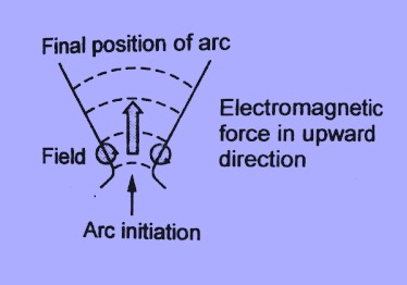
- Cooling the arc – Cooling helps in medium between the contacts. This increases the arc may be obtained by a gas resistance. Efficient cooling blast directed along the arc.
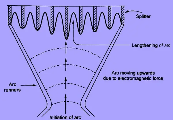
- Reducing X-section of the arc – If the area of X-section of the arc is reduced, the voltage necessary to maintain the arc is increased. In other words, the resistance of the arc path is increased. The cross-section of the arc can be reduced by letting the arc pass through a narrow opening or by having smaller area of contacts.
- Splitting the arc – The resistance of the arc can be increased by splitting the arc into a number of smaller arcs in series. Each one of these arcs experiences the effect of lengthening and cooling. The arc may be split by introducing some conducting plates between the contacts.
Low Resistance or Current zero Method
This method is employed for arc extinction in AC Circuits only. In this method, arc resistance is kept low until current zero where the arc extinguishes naturally and is prevented from restriking inspite of the rising voltage across the contacts.
All modern high power AC Circuit Breakers employ this method for arc extinction. In an AC system, current drops to zero after every half-cycle. At every current zero, the arc extinguishes for a brief moment.
Now the medium between the contacts contains ions and electrons so that it has small dielectric strength and can be easily broken down by the rising contact voltage known as restriking voltage.
If such a break-down does occur, the arc will persist for another half-cycle. If immediately after current zero, the dielectric strength of the medium between contacts is built up more rapidly than the voltage across the contacts, the arc fails to restrike and the current will be interrupted. The rapid increase of dielectric strength of the medium near current zero can be achieved by
- (a) causing the ionised particles in the space between contacts to recombine into neutral molecules.
- (b) sweeping the ionised particles away and replacing them by unionised particles.
Therefore, the real problem in AC arc interruption is to rapidly deionise the medium between contacts as soon as the current becomes zero so that the rising contact voltage or restriking voltage cannot breakdown the space between contacts. The de-ionisation of the medium can be achieved by :
- Lengthening of the gap : The dielectric strength of the medium is proportional to the length of the gap between contacts. Therefore, by opening the contacts rapidly, higher dielectric strength of the medium can be achieved.
- High pressure: If the pressure in the vicinity of the arc, is increased, the density of the particles constituting the discharge also increases. The increased density of particles causes higher rate of de-ionisation and consequently the dielectric strength of the medium between contacts is increased.
- Cooling: Natural combination of ionised particles takes place more rapidly if they are allowed to cool. Therefore, dielectric strength of the medium between the contacts can be increased by cooling the arc
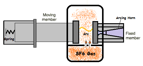
- Blast effect: If the ionised particles between the contacts are swept away and replaced by un-ionised particles, the dielectric strength of the medium can be increased consider-ably. This may be achieved by a gas blast directed along the discharge or by forcing oil into the contact space.






Comments are closed.