A fluorescent lamp converts electrical energy into useful light much more efficiently than incandescent lamps.
The luminous efficacy of a fluorescent light bulb can exceed 100 lumens per watt, several times the efficacy of an incandescent bulb with the comparable light output.
What’s Inside a Fluorescent Tube Light?
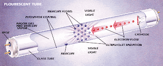
- A fluorescent lamp basically consists of a long glass gas discharge tube. Its inner surface is coated with phosphorous and is filled with inert gas, generally argon, with a trace of mercury.
- The tube is then finally sealed at low pressure with two filament electrodes each at its both ends.
- These electrode filaments are used to preheat the tube and initiate rapid conduction of electrons between the two end electrodes. The process initially requires a relatively high amount of power.
- The energy also converts some of the mercury from a liquid to a gas. Electrons then collide with the gaseous mercury atoms, increasing the amount of energy. As electrons return to their original energy level, they begin to release light. However, the light they emit is ultraviolet, and not visible to the naked eye, so another step needs to take place before we can see the light.
This is why the tube was coated with phosphorous. Phosphors will give off light when exposed to light. When exposed to the ultraviolet light, the particles emit a white light which we can see.
Once the conduction of electrons between the electrodes is complete, no more heating of the filaments is required and the whole system works at a much lower current.
How to Wire Fluorescent Lights
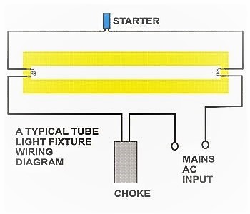
Here is one example of a tube light fixture consisting of a large heavy square “choke” or “ballast” and a small cylindrical “starter.” Let’s try to understand how the whole system with fluorescent light ballasts works. Please refer to the circuit diagram on the right as you read the following points:

- Fluorescent Light Circuit
- The choke is, in fact, a large inductor. It consists of a long copper winding over iron laminations.
- An inductor by nature always has a tendency to throw back the stored current in it, every time the power through it is switched OFF. This principle of the choke is exploited in lighting a fluorescent tube light.
- When an AC voltage is applied to a tube light fixture, the voltage passes through the choke, the starter, and the filaments of the tube.
- The filaments light up and instantly warm up the tube. The starter is made up of a discharge bulb with two electrodes next to it. When electricity passes through it an electrical arc is created between the two electrodes. This creates a light, however, the heat from the bulb causes one of the electrodes (a bimetallic strip) to bend, making contact with the other electrode. This stops the charged particles from creating the electrical arc that created light. However, now that the heat from the light is gone, the bimetallic strip cools and bends away from the electrode, opening the circuit again.
- At this point, the ballast or choke “kick’s back” it’s stored current, which again passes through the filaments and ignites the tube light once again.
- If the tube does not sufficiently charge up, subsequent kicks are delivered by the choke due to rapid switching of the starter, so that finally the tube strikes.
- After this, the choke only acts like a low impedance current limiter to the tube as long as the light is kept illuminated.
A common problem associated with these types of fixtures is humming or buzzing. The reason for this lies in the loosely fitted choke on to the fixture which vibrates in accordance with the 50 or 60-hertz frequency of our AC mains and creates a humming sort of noise. Tightening the choke’s screws may instantly eliminate the problem.
The working principle of today’s modern electronic ballasts is to avoid the use of starters for the preheating purpose. They are also very light in weight. These inhibit the initial flickering of the tube light as normally seen in the ordinary tube fixtures by changing the frequency of the mains power to a much higher 20,000 hertz or more. Moreover, electronic ballasts are very energy efficient.
Working of Fluorescent Lamp
If the (incident) free electron has enough kinetic energy, it transfers energy to the atom‘s outer electron, causing that electron to temporarily jump up to a higher energy level. The collision is ‘inelastic’ because a loss of kinetic energy occurs.
Most of the photons that are released from the mercury atoms have wavelengths in the ultraviolet (UV) region of the spectrum, predominantly at wavelengths of 253.7 and 185 nanometres (nm). These are not visible to the human eye, so they must be converted into visible light. This is done by making use of fluorescence.
Ultraviolet photons are absorbed by electrons in the atoms of the lamp’s interior fluorescent coating, causing a similar energy jump, then drop, with the emission of a further photon. The photon that is emitted from this second interaction has lower energy than the one that caused it.
The chemicals that make up the phosphor are chosen so that these emitted photons are at wavelengths visible to the human eye. The difference in energy between the absorbed ultra-violet photon and the emitted visible light photon goes toward heating up the phosphor coating.
When the light is turned on, the electric power heats up the cathode enough for it to emit electrons (thermionic emission). These electrons collide with and ionize noble gas atoms inside the bulb surrounding the filament to form a plasma by the process of impact ionization. As a result of avalanche ionization, the conductivity of the ionized gas rapidly rises, allowing higher currents to flow through the fluorescent lamp.
The fill gas helps determine the operating electrical characteristics of the lamp but does not give off light itself. The fill gas effectively increases the distance that electrons travel through the tube, which allows an electron a greater chance of interacting with a mercury atom.
Argon atoms, excited to a metastable state by the impact of an electron, can impart this energy to a neutral mercury atom and ionize it, described as the Penning effect.
This has the benefit of lowering the breakdown and operating voltage of the fluorescent lamp, compared to other possible fill gases such as krypton.




Comments are closed.