• Home
  • Courses
  • Machines
    • Transformer
    • AC Motors
      • Induction Motor
      • Synchronous Motor
    • DC Motor
    • DC Generator
  • Power System
    • Circuit Breaker
    • Switchgear
    • Substation
    • Control System
    • Measurement
  • Electronics
  • Blog
  • Contact
    • Contact Us
    • Privacy Policy
Have any question?
[email protected]
RegisterLogin
StudyElectrical.Com
  • Home
  • Courses
  • Machines
    • Transformer
    • AC Motors
      • Induction Motor
      • Synchronous Motor
    • DC Motor
    • DC Generator
  • Power System
    • Circuit Breaker
    • Switchgear
    • Substation
    • Control System
    • Measurement
  • Electronics
  • Blog
  • Contact
    • Contact Us
    • Privacy Policy

    Basic Electrical

    Working of Light Emitting Diode (LED)

    • Categories Basic Electrical, Electronics
    working led
    working led

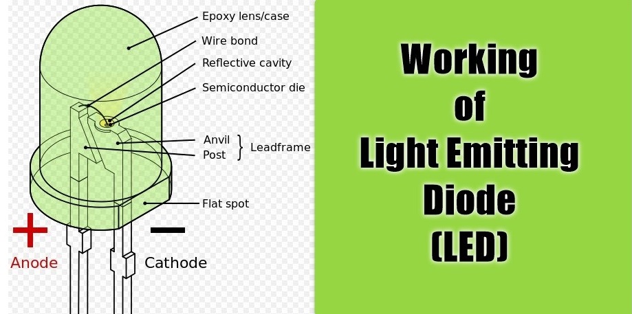
    A light-emitting diode (LED) is a diode that gives off visible light when forward biased.

    Light-emitting diodes are not made from silicon or germanium but are made by using elements like gallium, phosphorus and arsenic. By varying the quantities of these elements, it is possible to produce light of different wavelengths with colors that include red, green, yellow and blue.

    For example, when a LED is manufactured using gallium arsenide, it will produce red light. If the LED is made with gallium phosphide, it will produce a green light.

    Working Theory of LED

    When light-emitting diode (LED) is forward biased as shown in figure below, the electrons from the n-type material cross the pn junction and recombine with holes in the p-type material. 
     
    We know that these free electrons are in the conduction band and at a higher energy level than the holes in the valence band. 
    Capture
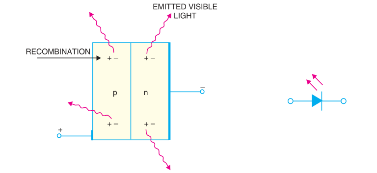
    When recombination takes place, the recombining electrons release energy in the form of heat and light. In germanium and silicon diodes, almost the entire energy is given up in the form of heat and emitted light is insignificant. 
     
    However, in materials like gallium arsenide, the number of photons of light energy is sufficient to produce quite intense visible light.

    The schematic symbol for a LED is shown in the above figure. The arrows are shown as pointing away from the diode, indicating that light is being emitted by the device when forward biased. 

    Although LEDs are available in several colours (red, green, yellow and orange are the most common), the schematic symbol is the same for all LEDs. There is nothing in the symbol to indicate the colour of a particular LED. 
    Capture

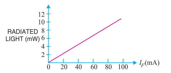
    This is a graph between radiated light and the forward current of the LED. It is clear from the graph that the intensity of radiated light is directly proportional to the forward current of LED.

    LED Voltage and Current

    The forward voltage ratings of most LEDs is from 1V to 3V and forward current ratings range from 20 mA to 100 mA. 


    Capture
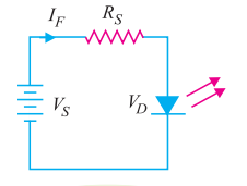
    In order that current  through the LED does not exceed the safe value, a resistor Rs is connected in series with it. The input voltage is Vs and the voltage across LED is Vⅆ.


    Capture%2B1


    Related Articles

    • Differences between Power Transformer and Distribution Transformer
      Working Principle of Transformer

      A transformer is a static piece of equipment used either for raising or lowering the…

    • DC Motor working 1
      Working Principle of DC Motor

      A DC motor is an electrical machine that converts electrical energy into mechanical energy. DC motor working…

    • working%2Bof%2Bmoving%2Bcoil
      Animated Video - Working of Moving Coil Instruments

      The animated video below explains the working of a moving coil instrument.

    • Automatic Light Controller arduino
      Arduino based Automatic Light Controller

      The automatic light controller offers energy saving and convenience in the areas with a photosensor…

    • ACB Air Circuit Breaker
      Working of Air Circuit Breakers

      What is an ACB? A circuit breaker in which the contacts open and close in…

    • working principle of alternator
      Working Principle of Alternator

      The machine which produces 3 phase power from mechanical power is called an alternator or…

    • Share:
    author avatar
    Electrical Engineer

    Previous post

    Core Type and Shell Type Transformers
    November 17, 2017

    Next post

    How Multicolor RGB (Red Green Yellow) LEDs Work?
    November 20, 2017

    You may also like

    dc bias characteristics of capacitor
    What is a capacitor’s DC bias characteristic?
    22 March, 2023
    passive components
    Understanding Passive Components in Electrical Engineering
    3 March, 2023
    used oscilloscope buying guide (1)
    Buying a Used Oscilloscope: A Guide to Help You Decide
    28 February, 2023

      1 Comment

    Leave A Reply Cancel reply

    Your email address will not be published. Required fields are marked *

    Search Here

    From Blog

    Open Delta Connection in Transformer
    Open Delta (V-V) Connection of Transformers
    21Nov2019
    The PCB Assembly Procedure Basic Information You Should Know
    The PCB Assembly Procedure- Basic Information You Should Know
    28Jun2022
    assignment
    Are New Standards Required Amid Electrical Safety Threats?
    05Jan2022
    electrolytic capacitors
    Electrolytic Capacitor – Types, Construction, Polarity and Leakage Current
    17Jul2020

    Categories

    • Alternator
    • Arduino
    • Basic Electrical
    • Battery
    • Books
    • Cables
    • Capacitor
    • Career
    • Circuit Breaker
    • Control System
    • DC Generator
    • DC Generator MCQ
    • DC Generator Solved Problems
    • DC Motor
    • DC Motor MCQ
    • Drives
    • Electric Vehicles
    • Electrical Circuits
    • Electrical Machines
    • Electrical Relays
    • Electrical Safety
    • Electronics
    • Embedded System
    • Exams
    • Generation
    • Guest Post
    • HVDC
    • Instrumentation
    • Interview Questions
    • Locomotives
    • MCQ
    • Measurement
    • Microcontroller
    • Objective Questions
    • PCB
    • PLC
    • Power System
    • Problems and Solution
    • Projects
    • Resistor
    • Signals and Systems
    • Single Phase Motors
    • Substation
    • Switchgear
    • Synchronous Motor
    • Three Phase Induction Motor
    • Transformer
    • Transmission Line
    • Uncategorized

    Copyright © 2021 Study Electrical, Inc.

    © StudyElectrical.Com 2021

    Login with your site account

    Lost your password?

    Not a member yet? Register now

    Register a new account

    Are you a member? Login now