The production of Rotating magnetic field in 3 phase supply is very interesting.
When a 3-phase winding is energized from a 3-phase supply, a rotating magnetic field is produced. This field is such that its poles do no remain in a fixed position on the stator but go on shifting their positions around the stator. For this reason, it is called a rotating field.
It can be shown that the magnitude of this rotating field is constant and is equal to 1.5 fm where fm is the maximum flux due to any phase.
A three-phase induction motor consists of three phases winding as its stationary part called stator. The three-phase stator winding is connected in star or delta.
The three-phase windings are displaced from each other by 120°. The windings are supplied by a balanced three phase ac supply.
The three-phase currents flow simultaneously through the windings and are displaced from each other by 120° electrical. Each alternating phase current produces its own flux which is sinusoidal.
So all three fluxes are sinusoidal and are separated from each other by 120°.
If the phase sequence of the windings is R-Y-B, then mathematical equations for the instantaneous values of the three fluxes ΦR , ΦY ,ΦB can be written as,
ΦR = Φmsin(ωt)
ΦY = Φmsin(ωt – 120)
ΦB = Φmsin(ωt – 240)
As windings are identical and supply is balanced, the magnitude of each flux is Φm .
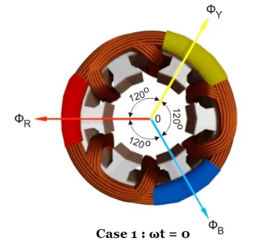
Case 1 : ωt = 0
ΦR = Φmsin(0) = 0
ΦY = Φmsin(0 – 120) = -0.866 Φm
ΦB = Φmsin(0 – 240) = +0.866 Φm
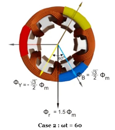
Case 2 : ωt = 60
ΦR = Φmsin(60) = +0.866 Φm
ΦY = Φmsin(- 60) = -0.866 Φm
ΦB = Φmsin(- 180) = 0
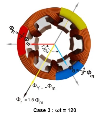
Case 3 : ωt = 120
ΦR = Φmsin(120) = +0.866 Φm
ΦY = Φmsin(0) = 0
ΦB = Φmsin(- 120) = -0.866 Φm
Case 4 : ωt = 180
ΦR = Φmsin(180) = 0
ΦY = Φmsin(60) = +.866 Φm
ΦB = Φmsin(- 60) = -0.866 Φm
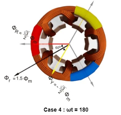
| Case 1 : ωt = 0 ΦR = Φmsin(0) = 0 ΦY = Φmsin(0 – 120) = -0.866 Φm ΦB = Φmsin(0 – 240) = +0.866 Φm | Case 2 : ωt = 60 ΦR = Φmsin(60) = +0.866 Φm ΦY = Φmsin(- 60) = -0.866 Φm ΦB = Φmsin(- 180) = 0 |
| Case 3 : ωt = 120 ΦR = Φmsin(120) = +0.866 Φm ΦY = Φmsin(0) = 0 ΦB = Φmsin(- 120) = -0.866 Φm | Case 4 : ωt = 180 ΦR = Φmsin(180) = 0 ΦY = Φmsin(60) = +.866 Φm ΦB = Φmsin(- 60) = -0.866 Φm |
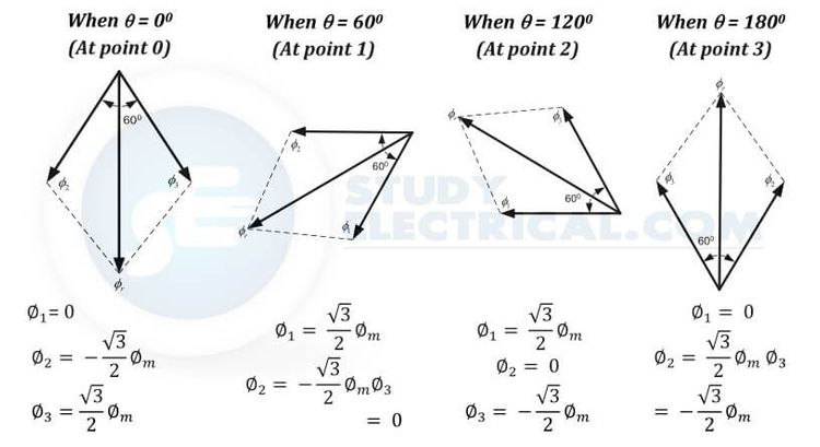
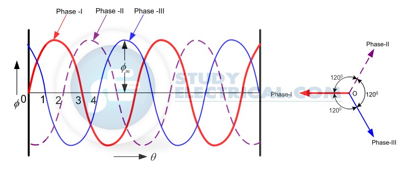
By comparing the electrical and phasor diagrams we can find the flux rotates one complete 360 degrees on the 180-degree displacement of flux.
Speed of Rotating Magnetic Field
The speed at which the rotating magnetic field revolves is called the synchronous speed (Ns).
Referring to the waveform of three phases, the time instant 4 represents the completion of one quarter cycle of alternating current Ix from the time instant 1.
During this one-quarter cycle, the field has rotated through 90°. At one complete cycle of current Ix from the origin, the field has completed one revolution.
Therefore, for a 2-pole stator winding, the field makes one revolution in one cycle of current. In a 4-pole stator winding, it can be shown that the rotating field makes one revolution in two cycles of current.
In general, for P poles, the rotating field makes one revolution in P/2 cycles of current.
$\therefore$ Cycles of Current $=\frac{P}{2} \times$ revolutions of field.
or Cycles of current per second $=\frac{P}{2} \times$ revolutions of field per second
Since revolutions per second is equal to the revolutions per minute (Ns ) divided by 60 and the number of cycles per second is the frequency f,
$f=\frac{P}{2} \times \frac{N_{S}}{60}=\frac{N_{S} P}{120}$
$\therefore \quad N_{S}=\frac{120 f}{P}$
The speed of the rotating magnetic field is the same as the speed of the alternator that is supplying power to the motor if the two have the same number of poles. Hence the magnetic flux is said to rotate at synchronous speed.
Direction of Rotating Magnetic Field
The phase sequence of the three-phase voltage applied to the stator winding in the first figure is R-Y-B.
If this sequence is changed to R-B-Y, it is observed that the direction of rotation of the field is reversed i.e., the field rotates counterclockwise rather than clockwise.
However, the number of poles and the speed at which the magnetic field rotates remain unchanged.
Thus it is necessary only to change the phase sequence in order to change the direction of rotation of the magnetic field. For a three-phase supply, this can be done by interchanging any two of the three lines.
As we shall see, the rotor in a 3-phase induction motor runs in the same direction as the rotating magnetic field.
Therefore, the direction of rotation of a 3-phase induction motor can be reversed by interchanging any two of the three motor supply lines.


Comments are closed.