Almost since day one, one or another type of PCB was a necessary component in electronics. Earlier it was used as mechanical support where electronics components were attached and wired separately. Later from being only mechanical support, PCBs started providing electrical connectivity. Modern rigid PCBs are more than mechanical support and connectivity. They can integrate electronic components such as antennas, inductors resistors and capacitors. Modern PCBs are designed to spread thermal energy to keep parts cool. In some cases, PCBs are used as design elements, front and back panels. Rigid PCBs dominates because of their manufacturing simplicity, low cost and high demand.
Modern electronics have changed significantly with the increasing demand for small, sophisticated and yet efficient devices. Small devices tend to have weird shapes and are packed with loads of electronics where conventional rigid PCBs start failing to fill this niche as is it cannot be bent, or be layered on top of each other without increasing thickness of device size.
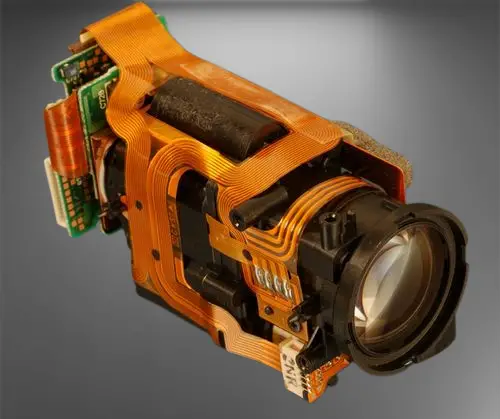
Earlier flex PCBs were used moderately in the limited number of applications due to increased expenses of limited manufacturing capabilities. You could see flex circuits on cameras and some phones.
However, things have changed once developers saw the potential of small, lightweight electronics. Manufacturers have put a significant effort in developing complex flexible and yet durable PCBs that can withstand harsh industrial conditions where temperature, pressure and chemical conditions occur.
What is Flex PCB?
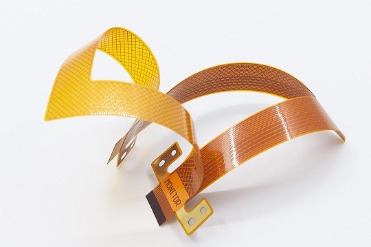
As the name implies, flex PCBs are flexible and can be bent to some level. Instead of using rigid material like FR4, flex PCBs are based on a thin PET or Polyamide film. Similarly, to rigid PCBs, flex PCBs can be single, double-sided and multilayered. Flexible material allows it to be folded into complex shapes that can fit into complex volumes of small devices. Flex PCBs enable electronic devices to be sculpted into natural and organic shapes.
Designing and building flex PCBs is still more costly than rigid PCBs. The manufacturing process requires more human interaction, additional materials such as stiffeners may be required, copper thickness also may vary in the areas of traces and connectors. However, in the long run, and large volumes, flex PCBs may become the more economical solution, as it requires fewer interconnections, many areas can be accomplished with single PCB rather than stitching multiple smaller ones.
Most common advantages of Flex PCBs are:
- They can be bent, transformed into any shape to fit specific enclosures
- Easy install as most of the components use flex connectors and snap connectors
- They can withstand higher temperatures and harsher environments than rigid PCBs
- Higher resistance to vibrations
- They are lighter and thinner to fit modern wearable and consumer electronics
- Being initially more costly than rigid, they can get cost-effective due to lack of multiple connectors
There are also several disadvantages of Flex PCBs:
- They are less resistant to static electricity
- Risk of overbending
- Risk of tearing
- Near to impossible to repair
- Increased initial cost
- Harder to automate manufacturing and assembly
No matter how good it sounds, flex PCBs alone is rarely used.
Rigid-Flex PCB tandem
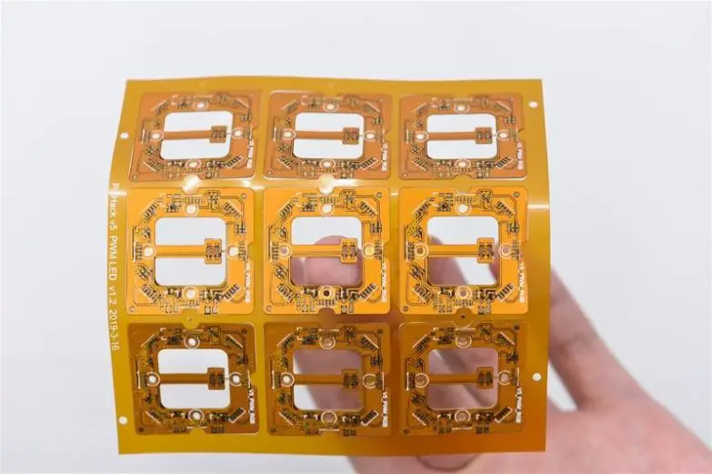
As most electronics components are rigid, soldering complex circuits on the flexible surface is not a good idea. It is hard to ensure proper solder joint quality, especially for more significant components. Additional stiffening on circuit areas may help, however, usually, only smaller footprint components are soldered on flexible regions. For more complex circuits a rigid-flex PCBs are used, where electronics are soldered on rigid parts of board and flex areas are used for connectivity.
The advantages of using Rigid-Flex PCB technology:
- Gives enough flexibility to fit the board into the device while maintaining the ability to bend and twist
- Reduced weight because rigid parts are used only in circuit areas
- It is designed without solder joints and connectors to increase durability and reliability
- It can withstand high temperatures and extreme conditions better than rigid-only boards due to the polyamide layer
- Less material required for assembly
- Better shock and vibration resistance
Disadvantages of Rigid-Flex PCBs:
- All the inherent problems from Flex PCBs as discussed above
- The fragile connection between rigid and flex parts
- Complex design and manufacturing
- Humidity may result in delamination
No matter all advantages, manufacturing of Rigid-Flex PCBs is more challenging because the designing process is taken to three-dimensional space. Also, several specific design rules need to be followed when designing flexible and rigid parts together. Let’s, go through several standard rules that need to be followed to design and build successful Rigid-Flex PCB:
- Place electronics components on rigid areas. Unless this is necessary, electronics components should be soldered on rigid parts to avoid tombstoning. This also allows having fewer layers of the flexible part.
- Traces should be distributed evenly in the flex part. Distributed traces allow getting better signal integrity and overall strength.
- Trace geometry should be constant in the bending area. Twisting and bending might impact the physical properties of the material, so be sure that bending and twisting impact all the same traces way. Keep traces round in bending areas to reduce the chance of tear.
- Avoid blind and buried vias in flex areas. This is an unnecessary complication for manufacturing. Also, blind or buried vias may bring problems due to detachment inside.
- Avoid sharp trace transitions near connectors and solder joints. Use a gradual transition from wide to narrow traces. This prevents the chance of tear and weak points.
- In multilayer flexible PCBs areas try to offset traces on opposite sides to achieve better mechanical properties and chances of cracking.
- Pads on flex PCB should have more copper area for better strength
- Avoid solid polygons on flex areas. The hatched filling is more flexible than solid pour.
Typical applications of Rigid-Flex PCBs
There are lots of benefits of using flex or rigid-flex PCBs. Extreme versatility comes with increased cost. Designing and manufacturing Rigid-Flex PCBs is more expensive and usually pays off in massive production or exceptional cases where a higher price is not the primary factor. They are common in military, aerospace, automotive and medical applications, but recently they appear more frequently in commercial products. Here are several circumstances where Rigid-Flex PCBs are an optimal solution:
- High-shock and vibration environments. Due to the flexible part, PCBs are resistant to shock and vibrations. Industrial machinery, scanning heads, spinning devices are the elements where rigid-flex PCBs are a cost-effective choice.
- Areas where connector failures would be fatal. Aeronautic applications, space or military demand on reliable electronics. If a simple connector failure between PCBs would bring significant consequences, the choice of Flex-Rigid is obvious.
- High-density electronics. Sometimes it is hard to put lots of electronics in tight spaces. As an example, we can satellite. It is very limited in size and weight, but there is a high demand for high functionality and redundancy. Rigid-Flex PCBs allows to reduce number of connectors, board sizes and weight significantly.
- Devices that require multiple rigid boards. Each board needs to be interconnected reliably and cheaply. A cost-effective solution is to use a single Rigid-Flex PCB to reduce cost and fit organically.
Rigid-Flex PCBs are ideal in significantly reducing the number of required connectors. This leads to less labour in assembly, better reliability in applications.
Flex-Rigid PCB manufacturing
The industry accepts Rigid-Flex PCBs well, and there is no surprise that almost every PCB fab house offers manufacturing and assembly services. The manufacturing capabilities are amazing. PCBWay is known to be a great PCB manufacturer China offering a wide range of services worldwide. They are dedicated to delivering high-quality product and services related to any type of PCBs from design to assembly and testing. PCBWay is known to be socially active with a large community where they organize multiple events, sales and giveaways. Probably this is not about the pricing, but how they treat each customer makes them stand out.
When looking at their ordering page, it seems they are covering all possible technologies related to Flex and Rigid-Flex PCBs. It is hard to outline the most important, but it is worth to mention several capabilities that make an impression of what can be achieved in for a relatively small price.
| Feature | Capability |
| Material | Polyimide Flex+FR4 |
| No of layers | Up to 10 (8 flex) |
| Min. Track/Spacing | 4mil |
| Min. Hole Size | 0.15mm |
| Rigid-Flex Thickness | 0.4-3.2mm |
| FPC Thickness | 0.08-0.4mm |
| Solder Mask Color (Rigid Part) | Green, Red, Yellow, Blue, White, Black, Purple, Matte Black, Matte green |
| Coverley (Flex Part) | Yellow, White, Black |
| Silkscreen | White, Black |
| Finish Cooper (Flex Part) | 0.5-2oz |
| Finish Cooper (Rigid Part) | 1-4oz |
| Via Process | Tenting Vias, Plugged Vias, Vias not covered |
| Additional Options | Half-Cut, Impedance Control |
| Build time | 10-20 days |
| Lead time | 2-3 days |
Besides prototyping and manufacturing, PCBWay is also specializing in assembly services so they could deliver finished and tested product to be put into the product right away.
Conclusion
Lots of small and smart devices such as laptops, smartwatches, wearables are possible thanks to revolutionary flex and Rigid-Flex PCBs. Reduced size and weight give a new edge to small, multifunctional devises. It appears that this trend is going to grow in the near future, which will lead to more robust and cost-effective manufacturing of Rigid-Flex PCBs.