• Home
  • Courses
  • Machines
    • Transformer
    • AC Motors
      • Induction Motor
      • Synchronous Motor
    • DC Motor
    • DC Generator
  • Power System
    • Circuit Breaker
    • Switchgear
    • Substation
    • Control System
    • Measurement
  • Electronics
  • Blog
  • Contact
    • Contact Us
    • Privacy Policy
Have any question?
[email protected]
RegisterLogin
StudyElectrical.Com
  • Home
  • Courses
  • Machines
    • Transformer
    • AC Motors
      • Induction Motor
      • Synchronous Motor
    • DC Motor
    • DC Generator
  • Power System
    • Circuit Breaker
    • Switchgear
    • Substation
    • Control System
    • Measurement
  • Electronics
  • Blog
  • Contact
    • Contact Us
    • Privacy Policy

Basic Electrical

Ohms Law – Simon Ohms Amazing Experiment and Results

  • Categories Basic Electrical
ohms law

We all learn Ohms law from our elementary school. This a magical formula that solves most of the problems in electrical engineering. 

Did you know who is George Simon Ohm and how he created this amazing formula? We will explain it today.

Table of Contents

  • Ohms Law Statement
    • Who is Georg Simon Ohm?
  • Ohms Experiment
  • Experiment Results
    • Related Articles

Ohms Law Statement

We all know Ohm’s Law deals with the relationship between voltage and current in an ideal conductor.

This relationship states that: The potential difference (voltage) across an ideal conductor is proportional to the current through it. The constant of proportionality is called the “resistance”, R. 

Read the difference between potential difference and Emf.

Ohm’s law states that the current through a conductor between two points is directly proportional to the voltage across the two points. Introducing the constant of proportionality, the resistance, one arrives at the usual mathematical equation that describes this relationship:

I = V/R
where I is the current through the conductor in units of amperes, 
V is the voltage measured across the conductor in units of volts, 
R is the resistance of the conductor in units of ohms.

More specifically, Ohm’s law states that the R in this relation is constant, independent of the current.

Who is Georg Simon Ohm?

Georg Simon Ohm a German physicist investigated the relationship between current and voltage in a resistor and published his experimental results in 1827.

Georg Simon Ohm (16 March 1789 – 6 July 1854) was a German physicist and mathematician. As a school teacher, Ohm began his research with the new electrochemical cell, invented by Italian scientist Alessandro Volta. 

Using equipment of his own creation, Ohm found that there is a direct proportionality between the potential difference (voltage) applied across a conductor and the resultant electric current. This relationship is known as Ohm’s law.

Ohms Experiment

A DC variable supply voltage is connected with a positive terminal at point a and negative terminal at ‘b’ as shown.

As voltage is increased, the current recorded by the ammeter increases.

For every voltage value, the current is recorded and the corresponding point is plotted on the rectangular graph.

Ohms Law Experimental Setup

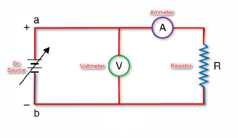
With this, a straight line graph passing through origin is obtained in the first quadrant.

Next the terminals of the variable dc supply are interchanged i.e. a is connected to -ve polarity of DC supply and b is connected to the +ve polarity of DC supply.

Since both the voltmeter and ammeter are moving coil, their individual connection should also be interchanged so that meters can read upscale. 

This has been done to reverse the direction of flow of current through the resistor R. Again the voltage is varied and corresponding to each voltage, the current is recorded and the pairs of V and I are plotted in the third quadrant.

Experiment Results

The experimental results indicate that there is a linear relationship between the current and voltage both in the first and third quadrant.

The slope of the straight line is also the same in both the quadrants which shows that the potential difference across the terminals of the conductor is proportional to the current passing through it i.e. V α I.

Ohms%2Blaw%2Bresults

Also, it is found that for a constant current in the conductor resistance should be changed proportionally to the potential difference i.e. V α R.

Combining the two proportionalities, we have

V α IR

or V= kIR

where k is a constant of proportionality.

However, the units of voltage, current and resistance are defined so that the value of k = 1. When the current is 1 amp, voltage 1 volt, the resistance is 1 Ω.

1 = k . 1 . 1

Thus the equation becomes

V= IR

The equation explains ohm’s law which is stated as follows :

  • The resistances which Ohm considered are linear.
    • i.e. the resistances which have linear V-I characteristic.
  • Also, these are bilateral
    • i.e. irrespective of the direction of flow of current the resistance does not charge.
  • Physical condition (Temperature, Pressure etc.) of the conductor remaining constant, the voltage across the terminals of a conductor is proportional to the current flowing through it.


Related Articles

  • engineering students working in the lab PESV4KM
    What do Electrical Engineers Do?

    An electrical engineer is someone who designs and develops new electrical equipment, solves problems and…

  • ELECTRICAL IMPEDANCE MADE EASY
    Video Tutorial: Electrical Impedance - A Practical View

    In this two part video series we discuss the basics of electrical impedance from a…

  • 4 2Bmajor 2Btypes 2Bof 2Bsubstations
    4 Major Types of Electrical Substations

      The assembly of the apparatus used to change some characteristic (e.g. voltage, a.c. to…

  • types of electrical relays
    Types of Electrical Relays

    We have already discussed the working of electrical relays. Now we are going through different…

  • electrical noise motor
    Electrical and Mechanical Noise in Motors

    Two types of noises occur in an electric motor, one is electrical noise and the…

  • GFCI Wiring
    Systems of Wiring - Introduction to Electrical Wiring

    The types of internal wiring usually employed are: Cleat wiring: Wooden Casing and Capping Wiring…

  • Share:
author avatar
Electrical Engineer

Previous post

Functional Characteristics of Protective Relaying
November 11, 2015

Next post

Series and Parallel Circuits - A Water Analogy
November 15, 2015

You may also like

Thin film application iin electronics
The Various Applications Of Thin Films In Electronics And Other Equipment
16 January, 2023
Thin film resistors
Applications & Functions of Thin Film Resistors
12 January, 2023
Si units types advantages and disadvantages (1)
SI Units (International System of Units): Types, Advantages and Disadvantages
11 June, 2022

    1 Comment

Leave A Reply Cancel reply

Your email address will not be published. Required fields are marked *

Search Here

From Blog

armature-reaction-dc-generator
Armature Reaction in DC Generator
01Sep2014
load forecasting in power system
Load Forecasting – Purpose, Classification and Procedure
26May2016
Moving Iron Instruments Banner
Moving Iron Instruments – Attraction and Repulsion Type
24Nov2019
Series Combination of Resistances
3 Combination of Resistances Explained – (Series, Parallel and Series Parallel)
21Nov2019

Categories

  • Alternator
  • Arduino
  • Basic Electrical
  • Battery
  • Books
  • Cables
  • Capacitor
  • Career
  • Circuit Breaker
  • Control System
  • DC Generator
  • DC Motor
  • Drives
  • Electric Vehicles
  • Electrical Circuits
  • Electrical Machines
  • Electrical Relays
  • Electrical Safety
  • Electronics
  • Embedded System
  • Exams
  • Generation
  • Guest Post
  • HVDC
  • Instrumentation
  • Interview Questions
  • Locomotives
  • Measurement
  • Microcontroller
  • Objective Questions
  • PCB
  • PLC
  • Power System
  • Problems and Solution
  • Projects
  • Resistor
  • Signals and Systems
  • Single Phase Motors
  • Substation
  • Switchgear
  • Synchronous Motor
  • Three Phase Induction Motor
  • Transformer
  • Transmission Line
  • Uncategorized

Copyright © 2021 Study Electrical, Inc.

© StudyElectrical.Com 2021

Login with your site account

Lost your password?

Not a member yet? Register now

Register a new account

Are you a member? Login now