• Home
  • Courses
  • Machines
    • Transformer
    • AC Motors
      • Induction Motor
      • Synchronous Motor
    • DC Motor
    • DC Generator
  • Power System
    • Circuit Breaker
    • Switchgear
    • Substation
    • Control System
    • Measurement
  • Electronics
  • Blog
  • Contact
    • Contact Us
    • Privacy Policy
Have any question?
[email protected]
RegisterLogin
StudyElectrical.Com
  • Home
  • Courses
  • Machines
    • Transformer
    • AC Motors
      • Induction Motor
      • Synchronous Motor
    • DC Motor
    • DC Generator
  • Power System
    • Circuit Breaker
    • Switchgear
    • Substation
    • Control System
    • Measurement
  • Electronics
  • Blog
  • Contact
    • Contact Us
    • Privacy Policy

    Power System

    Functional Characteristics of Protective Relaying

    • Categories Power System, Electrical Relays, Substation
    fundamental requirements of protective relaying

    fundamental%2Brequirements%2Bof%2Bprotective%2Brelaying

    The principal function of protective relaying is to cause the prompt removal from service of any element of the power system when it starts to operate in an abnormal manner or interfere with the effective operation of the rest of the system. 

    In order that protective relay system may perform this function satisfactorily, it should have the following qualities :

    1. Selectivity 
    2. Speed 
    3. Sensitivity
    4. Reliability
    5. Simplicity
    6. Economy

    Table of Contents

    • Selectivity
    • Speed
    • Sensitivity
    • Reliability
    • Simplicity
    • Economy
    • Related Articles

    Selectivity

    It is the ability of the protective system to select correctly that part of the system in trouble and disconnect the faulty part without disturbing the rest of the system.

    • A well designed and efficient relay system should be selective i.e. it should be able to detect the point at which the fault occurs and cause the opening of the circuit breakers closest to the fault with minimum or no damage to the system. 
    This can be illustrated by referring to the single line diagram of a portion of a typical power system shown in the figure below. It may be seen that circuit breakers are located in the connections to each power system elements in order to make it possible to disconnect only the faulty section.

    If a fault occurs at bus-bars on the last zone, then only breakers nearest to the fault viz. 10, 11, 12 and 13 should open. In fact, the opening of any other breaker to clear the fault will lead to a greater part of the system being disconnected.

    requirments%2Bof%2Bprotective%2Brelay
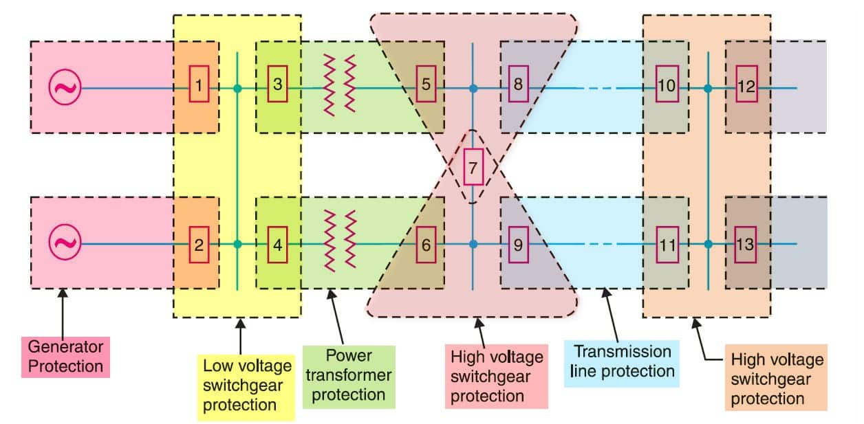
    Single Line Diagram of a portion of Power System

    In order to provide selectivity to the system, it is a usual practice to divide the entire system into several protection zones. When a fault occurs in a given zone, then only the circuit breakers within that zone will be opened. This will isolate only the faulty circuit or apparatus, leaving the healthy circuits intact. 

    The system can be divided into the following protection zones :

    • (a) generators 
    • (b) low-tension switchgear 
    • (c) transformers
    • (d) high-tension switchgear 
    • (e) transmission lines

    It may be seen in the above figure that there is a certain amount of overlap between the adjacent protection zones. For a failure within the region where two adjacent zones overlap, more breakers will be opened than the minimum necessary to disconnect the faulty section. 

    But if there were no overlap, a failure in the region between zones would not lie in either region and, therefore, no breaker would be opened. For this reason, a certain amount of overlap is provided between the adjacent zones.

    Speed

    The relay system should disconnect the faulty section as fast as possible for the following reasons :
    • Electrical apparatus may be damaged if they are made to carry the fault currents for a long time.
    • A failure on the system leads to a great reduction in the system voltage. If the faulty section is not disconnected quickly, then the low voltage created by the fault may shut down consumers motors and the generators on the system may become unstable.
    • The high-speed relay system decreases the possibility of development of one type of fault into the other more severe type.
    The ultimate goal of protective relaying is to disconnect a faulty system element as quickly as possible. Sensitivity and selectivity are essential to assuring that the proper circuit breakers will be tripped, but speed is the ‘pay-off’.

    Sensitivity

    It is the ability of the relay system to operate with a low value of actuating quantity.

    The sensitivity of a relay is a function of the volt-amperes input to the coil of the relay necessary to cause its operation.

    • The smaller the volt-ampere input required to cause relay operation, the more sensitive is the relay. 

    Thus, a 1 VA relay is more sensitive than a 3 VA relay. It is desirable that the relay system should be sensitive so that it operates with low values of volt-ampere input.

    Reliability

    It is the ability of the relay system to operate under pre-determined conditions. Without reliability, the protection would be rendered largely ineffective and could even become a liability.

    That protective-relaying equipment must be reliable is a basic requirement. When protective relaying fails to function properly, the allied mitigation features are largely ineffective.

    Therefore, it is essential that protective-relaying equipment be inherently reliable, and that its application, installation, and maintenance be such as to assure that its maximum capabilities will be realized.

    Simplicity

    The relaying system should be simple so that it can be easily maintained. Reliability is closely related to simplicity. The simpler the protection scheme, the greater will be its reliability.

    Economy

    The most important factor in the choice of a particular protection scheme is the economic aspect. Sometimes it is economically unjustified to use an ideal scheme of protection and a compromise method has to be adopted. 

    • As a rule, the protective gear should not cost more than 5% of the total cost. 
    However, when the apparatus to be protected is of utmost importance (e.g. generator, main transmission line etc.), economic considerations are often subordinated to reliability.
     

    Related Articles

    • Substation Relay
      Basics of Protective Relaying in Power System

      Protective relaying is necessary with almost every electrical plant, and no part of the power…

    • protective zones in power system
      Protective Zones in Power Systems

      In this post, we will look into protective zones in the power system and why…

    • fUNCTION OF PROTECTIVE RELAYS
      Function of Protective Relays in Power System

      We usually think of an electric power system in terms of its more impressive parts…

    • Protective relay working
      What are Protective Relays? | Types and Working

      What is a Protective Relay? The protective relay was invented more than 160 years ago.…

    • DC Shunt Generator Characteristics
      Characteristics of DC Shunt Generator

      In this article, you will learn the characteristics of a dc shunt generator. A shunt…

    • dc generator open circuit characteristics
      DC Generator Characteristics

      DC generator characteristics are the relations between excitation, terminal voltage and load exhibited graphically by means…

    • Share:
    author avatar
    Electrical Engineer

    Previous post

    Basic Types of Current Transformers
    November 11, 2015

    Next post

    Ohms Law - Simon Ohms Amazing Experiment and Results
    November 11, 2015

    You may also like

    Transformer testing at factory
    Percentage Reactance in Power System (Transformer, Generator or Reactor)
    16 January, 2023
    Load Curve and Load Duration Curve
    Load Duration Curve in Power Station
    29 September, 2022
    Double end break disconnect switch
    Disconnect Switches (Isolator) in Substation: Types, Design and Working
    1 September, 2022

    Leave A Reply Cancel reply

    Your email address will not be published. Required fields are marked *

    Search Here

    From Blog

    MIT 6.003 Signals and Systems Course
    What is Signal? | Definition, Types and Examples
    30Aug2022
    universal motor construction
    Construction of Universal Motors
    03Dec2014
    Electric motor maintenance
    Electric Motor Maintenance : Preventive, Predictive and Reactive Maintenance
    12Sep2014
    dc motor troubles
    4 Major Troubles in a DC Motor with Reasons
    21May2014

    Categories

    • Alternator
    • Arduino
    • Basic Electrical
    • Battery
    • Books
    • Cables
    • Capacitor
    • Career
    • Circuit Breaker
    • Control System
    • DC Generator
    • DC Generator MCQ
    • DC Generator Solved Problems
    • DC Motor
    • DC Motor MCQ
    • Drives
    • Electric Vehicles
    • Electrical Circuits
    • Electrical Machines
    • Electrical Relays
    • Electrical Safety
    • Electronics
    • Embedded System
    • Exams
    • Generation
    • Guest Post
    • HVDC
    • Instrumentation
    • Interview Questions
    • Locomotives
    • MCQ
    • Measurement
    • Microcontroller
    • Objective Questions
    • PCB
    • PLC
    • Power System
    • Problems and Solution
    • Projects
    • Resistor
    • Signals and Systems
    • Single Phase Motors
    • Substation
    • Switchgear
    • Synchronous Motor
    • Three Phase Induction Motor
    • Transformer
    • Transmission Line
    • Uncategorized

    Copyright © 2021 Study Electrical, Inc.

    © StudyElectrical.Com 2021

    Login with your site account

    Lost your password?

    Not a member yet? Register now

    Register a new account

    Are you a member? Login now