Time domain analysis and frequency domain analysis are two approaches used to study the behavior of systems, including control systems. Here are their key differences, along with simple examples to illustrate each approach:
Time Domain Analysis
Time domain analysis focuses on analyzing the system’s behavior in the time domain. It involves studying the response of a system to changes or disturbances over time. Here, the input and output signals are represented as functions of time.
Example: Consider a simple RC circuit with a resistor and a capacitor in series. If you apply a step input voltage to the circuit, time domain analysis allows you to observe the transient response of the circuit, including how the voltage across the capacitor changes over time until it reaches a steady-state value.
Frequency Domain Analysis
Frequency domain analysis, on the other hand, explores the system’s behavior in the frequency domain. It involves analyzing how the system responds to different frequencies of input signals. Here, the input and output signals are represented as functions of frequency.
Example: Let’s take a second-order mechanical system, such as a mass-spring-damper system. By applying a sinusoidal force input at different frequencies, frequency domain analysis allows you to determine how the system’s response (displacement or velocity) varies with frequency. This analysis can provide insights into the system’s resonance behavior or frequency-dependent gain and phase shifts.
Comparing Time and Frequency Domain Analysis
Lets compare Time and Frequency Domain Analysis.
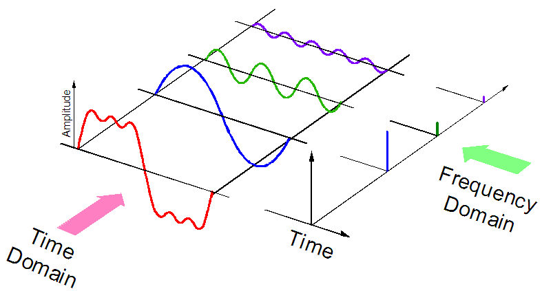
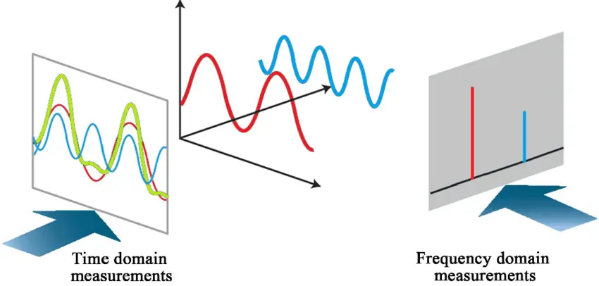
- Representation: In time domain analysis, signals are represented as functions of time, while in frequency domain analysis, signals are represented as functions of frequency.
- Focus: Time domain analysis emphasizes the transient response of a system, studying how the system behaves over time. Frequency domain analysis, on the other hand, focuses on the steady-state response and examines how the system responds to different frequencies.
- Techniques: Time domain analysis involves differential equations, convolution, and time response analysis techniques. Frequency domain analysis involves Laplace transforms, transfer functions, and frequency response analysis techniques.
- Information: Time domain analysis provides information about the system’s behavior over time, including its stability, settling time, overshoot, and response to disturbances. Frequency domain analysis provides information about the system’s gain, phase shift, resonant frequencies, and frequency-dependent behavior.
Here’s a table summarizing the key differences between time domain analysis and frequency domain analysis:
| Time Domain Analysis | Frequency Domain Analysis | |
|---|---|---|
| Focus | Transient response | Steady-state response and frequency-dependent behavior |
| Signals | Functions of time | Functions of frequency |
| Techniques | Differential equations, convolution, time response analysis | Laplace transforms, transfer functions, frequency response analysis |
| Information | Stability, settling time, overshoot, response to disturbances | Gain, phase shift, resonant frequencies, frequency-dependent behavior |
| Example | Observing the transient response of an RC circuit | Analyzing the steady-state response of a mass-spring-damper system at different frequencies |
Differences between Time and Frequency Domain Analysis
Here are some additional points based on the provided text:
Time Domain Analysis:
- Interpretation: Time domain analysis provides a direct interpretation of the system’s behavior. It works with a more accurate mathematical model using techniques like Laplace transform.
- Response Components: The complete response in time domain analysis includes both the transient response (initial response to a change) and the steady-state response (long-term behavior after transients have settled).
- Stability Analysis: Two commonly used methods for stability analysis in time domain analysis are the Root locus method and the Routh-Hurwitz criteria.
- Performance Parameters: Parameters such as pole and zero locations, rise time, peak time, settling time, delay time, damping factor, natural frequency, and damped frequency are considered in time domain analysis.
- Design: Designing control systems in the time domain often involves a trial-and-error approach, iterating and adjusting parameters to achieve desired performance.
Frequency Domain Analysis:
- Interpretation: Frequency domain analysis provides an indirect interpretation of the system’s behavior. It relies on less accurate mathematical models but offers robustness.
- Steady-State Response: In frequency domain analysis, if the input signal is sinusoidal, the frequency response directly reveals the system’s steady-state response at that frequency.
- Stability Analysis: Three commonly used methods for stability analysis in frequency domain analysis are the Bode plot, Nyquist plot, and pole placement methods.
- Performance Parameters: Parameters such as bandwidth, resonant peak overshoot, resonant frequency, gain margin, phase margin, gain and phase crossover frequencies are considered in frequency domain analysis.
- Design: Designing control systems in the frequency domain often involves the use of compensators like Lag, Lead, or Lead-Lag to shape the frequency response and meet desired specifications. Trial-and-error methods may also be employed.
Overall: Both time domain analysis and frequency domain analysis have their advantages and are effective for control system synthesis. The choice between the two depends on the expertise, system characteristics, and design requirements.
Here’s an updated table summarizing the additional points.
| Time Domain Analysis | Frequency Domain Analysis | |
|---|---|---|
| Interpretation | Direct interpretation | Indirect interpretation |
| Mathematical Model | Accurate model (Laplace transform) | Less accurate model, but robust |
| Response Components | Transient + Steady-state response | Steady-state response |
| Stability Analysis | Root locus, Routh-Hurwitz criteria | Bode plot, Nyquist plot, pole placement methods |
| Performance Parameters | Poles, Zeros, Rise time, Peak time, Settling time, Delay time, Damping factor, Natural frequency, Damped frequency | Encirclement of -1+j0 in G(s)H(s) plane, Bandwidth, Resonant peak overshoot, Resonant frequency, Gain margin, Phase margin, Gain and Phase crossover frequency |
| Design Approach | Trial and error | Lag, Lead, Lead-Lag compensation with trial and error |
| Advantages | Accurate interpretation, complete response consideration | Reveals steady-state response, specific frequency analysis |
| System Realization | – | Verbal ease in realization for experts in frequency domain |
Remember that these points provide a simplified comparison, and there may be additional aspects and techniques associated with each analysis method.
Conclusion
It’s important to note that time domain and frequency domain analyses are complementary. Time domain analysis is useful for understanding the system’s dynamic behavior, while frequency domain analysis helps identify frequency-specific characteristics and design controllers that can shape the system’s response to different frequencies.