
In this post, we will explain Instantaneous, Inverse Time and Definite Time Lag Relays and their characteristics.
An important characteristic of a relay is its time of operation. By ‘the time of operation’ is meant length of the time from the instant when the actuating element is energized to the instant when the relay contacts are closed.
Sometimes it is desirable and necessary to control the operating time of a relay. For this purpose, mechanical accessories are used with relays.
Instantaneous Relay
An instantaneous relay is one in which no intentional time delay is provided. In this case, the relay contacts are closed immediately after the current in the relay coil exceeds the minimum calibrated value.
 Figure shows an instantaneous solenoid type of relay. Although there will be a short time interval between the instant of pickup and the closing of relay contacts, no intentional time delay has been added.
 The instantaneous relays have operating time less than 0·1 second. The instantaneous relay is effective only where the impedance between the relay and the source is small compared to the protected section impedance.
The operating time of instantaneous relay is sometimes expressed in cycles based on the power system frequency.
e.g. one-cycle would be 1/50 second in a 50-cycle system.
Inverse Time Relay
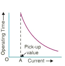
An inverse-time relay is one in which the operating time is approximately inversely proportional to the magnitude of the actuating quantity.
The figure shows the time-current characteristics of an inverse current relay. At values of current less than the pickup, the relay never operates. At higher values, the time of operation of the relay decreases steadily with the increase of current.
 The inverse-time delay can be achieved by associating mechanical accessories with relays.
- In an induction relay, the inverse-time delay can be achieved by positioning a permanent magnet (known as a drag magnet) in such a way that relay disc cuts the flux between the poles of the magnet. When the disc moves, currents set up in it produce a drag on the disc which slows its motion.
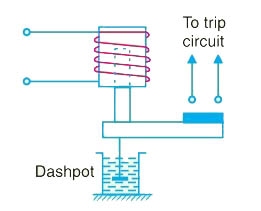
- In other types of relays, the inverse time delay can be introduced by oil dashpot or a timelimit fuse. Figure shows an inverse time solenoid relay using oil dashpot. The piston in the oil dashpot attached to the moving plunger slows its upward motion. At a current value just equal to the pickup, the plunger moves slowly and time delay is at a maximum. At higher values of relay current, the delay time is shortened due to greater pull on the plunger.
The inverse-time characteristic can also be obtained by connecting a time-limit fuse in parallel with the trip coil terminals as shown in the figure below.
 The shunt path formed by time-limit fuse is of negligible impedance as compared with the relatively high impedance of the trip coil. Therefore, so long as the fuse remains intact, it will divert practically the whole secondary current of CT from the trip coil.
 When the secondary current exceeds the current carrying capacity of the fuse, the fuse will blow and the whole current will pass through the trip coil, thus opening the circuit breaker. The timelag between the incidence of excess current and the tripping of the breaker is governed by the characteristics of the fuse. Careful selection of the fuse can give the desired inverse-time characteristics, although the necessity for replacement after an operation is a disadvantage.
Definite Time Lag Relay
In this type of relay, there is a definite time elapse between the instant of pickup and the closing of relay contacts. This particular time setting is independent of the amount of current through the relay coil ; being the same for all values of current in excess of the pickup value.
It may be worthwhile to mention here that practically all inverse-time relays are also provided with definite minimum time feature in order that the relay may never become instantaneous in its action for very long overloads.