• Home
  • Courses
  • Machines
    • Transformer
    • AC Motors
      • Induction Motor
      • Synchronous Motor
    • DC Motor
    • DC Generator
  • Power System
    • Circuit Breaker
    • Switchgear
    • Substation
    • Control System
    • Measurement
  • Electronics
  • Blog
  • Contact
    • Contact Us
    • Privacy Policy
Have any question?
[email protected]
RegisterLogin
StudyElectrical.Com
  • Home
  • Courses
  • Machines
    • Transformer
    • AC Motors
      • Induction Motor
      • Synchronous Motor
    • DC Motor
    • DC Generator
  • Power System
    • Circuit Breaker
    • Switchgear
    • Substation
    • Control System
    • Measurement
  • Electronics
  • Blog
  • Contact
    • Contact Us
    • Privacy Policy

Alternator

4 Advantages of Stationary Armature in Alternator

  • Categories Alternator
Armature of Alternator

An alternator operates on the same fundamental principle of electromagnetic induction as a DC generator i.e., when the flux linking a conductor changes, an e.m.f. is induced in the conductor. 

Like a DC generator, an alternator also has an armature winding and a field winding. But there is one important difference between the two.

In a DC generator, the armature winding is placed on the rotor in order to provide a way of converting alternating voltage generated in the winding to a direct voltage at the terminals through the use of a rotating commutator. 

The field poles are placed on the stationary part of the machine. Since no commutator is required in an alternator, it is usually more convenient and advantageous to place the field winding on the rotating part (i.e., rotor) and armature winding on the stationary part (i.e., stator).

Advantages of Stationary Armature

The field winding of an alternator is placed on the rotor and is connected to DC supply through two slip rings.
Armature of Alternator

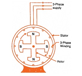
The 3-phase armature winding is placed on the stator. This arrangement has the following advantages:

Untitled 2

  1. It is easier to insulate stationary winding for high voltages for which the alternators are usually designed. It is because they are not subjected to centrifugal forces and also extra space is available due to the stationary arrangement of the armature.
  2. The stationary 3-phase armature can be directly connected to load without going through large, unreliable slip rings and brushes.
  3. Only two slip rings are required for d.c. supply to the field winding on the rotor. Since the exciting current is small, the slip rings and brush gear required are of light construction.
  4. Due to the simple and robust construction of the rotor, the higher speed of rotating DC field is possible. This increases the output obtainable from a machine of given dimensions.

Note: All alternators above 5 kVA employ a stationary armature (or stator) and a revolving d.c. field.

Related Articles

  • effects of armature reaction in alternator
    Armature Reaction in Alternator

    Armature reaction in alternator is the effect of armature flux on the field flux (i.…

  • 3d printed alternator
    3D Printed Alternator for Educational Purposes - Video

    This is a 99% 3D printed FULL SCALE Alternator made for educational purposes.

  • working principle of alternator
    Working Principle of Alternator

    The machine which produces 3 phase power from mechanical power is called an alternator or…

  • adcmotor
    Armature Reaction in DC Motors

    Armature reaction also occurs in a DC motor just like armature reaction in DC Generator.…

  • Dc machine generator and motor construction
    Advantages of Operating DC Generators in Parallel

    In a DC power plant, power is usually supplied from several generators of small ratings…

  • Drum wound armature of dc motor
    Gramme Ring and Drum Wound Armature in DC Motors

    A DC motor can be made using different types of armatures based on its application.…

  • Share:
author avatar

Previous post

Compensating Windings and Interpoles in DC Machines

Next post

Back EMF and Its Significance in DC Motor

You may also like

C
How Titanium Can Contribute To Clean Energy Production
Induction Motor and Transformer
Comparison between Induction Motor and Transformer
3d printed alternator
3D Printed Alternator for Educational Purposes – Video

    1 Comment

  1. Vikas Sahu
    January 28, 2020
    Reply

    Better explanation…

Leave A Reply Cancel reply

Your email address will not be published. Required fields are marked *

Search Here

From Blog

Practical 2Btransformer 2Bon 2Bno 2Bload
Practical Transformer on No Load
How does tesla electric car work
Video : How Does a Tesla Electric Car Work?
core-type-transformer
Core Type and Shell Type Transformers
how to build a power supply unit
Design a Power Supply Circuit – Simple to Complex

Categories

  • Alternator
  • Arduino
  • Basic Electrical
  • Battery
  • Books
  • Cables
  • Capacitor
  • Career
  • Circuit Breaker
  • Control System
  • DC Generator
  • DC Motor
  • Electric Vehicles
  • Electrical Circuits
  • Electrical Machines
  • Electrical Relays
  • Electrical Safety
  • Electronics
  • Embedded System
  • Exams
  • Generation
  • Guest Post
  • HVDC
  • Instrumentation
  • Interview Questions
  • Locomotives
  • Measurement
  • Microcontroller
  • Objective Questions
  • PCB
  • PLC
  • Power System
  • Projects
  • Signals and Systems
  • Single Phase Motors
  • Substation
  • Switchgear
  • Synchronous Motor
  • Three Phase Induction Motor
  • Transformer
  • Transmission Line
  • Uncategorized

Copyright © 2021 Study Electrical, Inc.

© StudyElectrical.Com 2021

Login with your site account

Lost your password?

Not a member yet? Register now

Register a new account

Are you a member? Login now