A three phase induction motor has two main parts
- stator
- rotor.
The rotor is separated from the stator by a small air-gap which ranges from 0.4 mm to 4 mm, depending on the power of the motor.
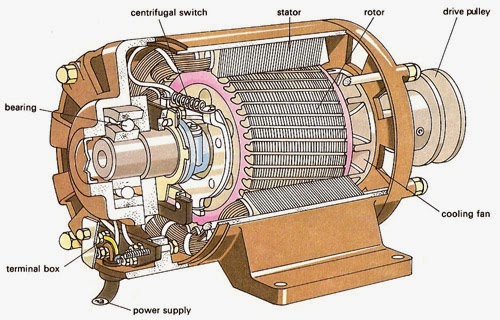
Stator of Three Phase Induction Motor
It consists of a steel frame which encloses a hollow, cylindrical core made up of thin laminations of silicon steel to reduce hysteresis and eddy current losses.
A number of evenly spaced slots are provided on the inner periphery of the laminations. The insulated connected to form a balanced 3-phase star or delta connected circuit.
The three-phase stator winding is wound for a definite number of poles as per the requirement of speed. Greater the number of poles, lesser is the speed of the motor and vice-versa.
When three phase supply is given to the stator winding, a rotating magnetic field of constant magnitude is produced. This rotating field induces currents in the rotor by electromagnetic induction.
Rotor of Three Phase Induction Motor
The winding placed in these slots (called rotor winding) may be one of the following two types:
- Squirrel cage type Rotor
- Wound type Rotor
Squirrel cage rotor
It consists of a laminated cylindrical core having parallel slots on its outer periphery. One copper or aluminum bar is placed in each slot. All these bars are joined at each end by metal rings called end rings.
This forms a permanently short-circuited winding which is indestructible. The entire construction (bars and end rings) resembles a squirrel cage and hence the name.
The rotor is not connected electrically to the supply but has current induced in it by transformer action from the stator. Those induction motors which employ squirrel cage rotor are called squirrel cage induction motors.
Most of three phase induction motor use squirrel cage rotor as it has a remarkably simple and robust construction enabling it to operate in the most adverse circumstances.
However, it suffers from the disadvantage of a low starting torque. It is because the rotor bars are permanently short-circuited and it is not possible to add any external resistance to the rotor circuit to have a large starting torque.
Wound rotor
It consists of a laminated cylindrical core and carries a 3-phase winding, similar to the one on the stator. The rotor winding is uniformly distributed in the slots and is usually star-connected.
The open ends of the rotor winding are brought out and joined to three insulated slip rings mounted on the rotor shaft with one brush resting on each slip ring.
The three brushes are connected to a three phase star-connected rheostat. At starting, the external resistances are included in the rotor circuit to give a large starting torque.
These resistances are gradually reduced to zero as the motor runs up to speed. The external resistances are used during starting period only. When the motor attains normal speed, the three brushes are short-circuited so that the wound rotor runs like a squirrel cage rotor.