• Home
  • Courses
  • Machines
    • Transformer
    • AC Motors
      • Induction Motor
      • Synchronous Motor
    • DC Motor
    • DC Generator
  • Power System
    • Circuit Breaker
    • Switchgear
    • Substation
    • Control System
    • Measurement
  • Electronics
  • Blog
  • Contact
    • Contact Us
    • Privacy Policy
Have any question?
[email protected]
Login
StudyElectrical.Com
  • Home
  • Courses
  • Machines
    • Transformer
    • AC Motors
      • Induction Motor
      • Synchronous Motor
    • DC Motor
    • DC Generator
  • Power System
    • Circuit Breaker
    • Switchgear
    • Substation
    • Control System
    • Measurement
  • Electronics
  • Blog
  • Contact
    • Contact Us
    • Privacy Policy

    Electrical Machines

    Production of Rotating Magnetic Field

    • Categories Electrical Machines, Alternator, Synchronous Motor, Three Phase Induction Motor
    Phasor diagram of three phase

    The production of Rotating magnetic field in 3 phase supply is very interesting.

    When a 3-phase winding is energized from a 3-phase supply, a rotating magnetic field is produced. This field is such that its poles do no remain in a fixed position on the stator but go on shifting their positions around the stator. For this reason, it is called a rotating field.

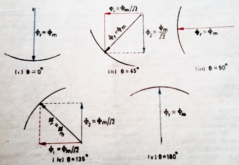
    It can be shown that the magnitude of this rotating field is constant and is equal to 1.5 fm where fm is the maximum flux due to any phase.

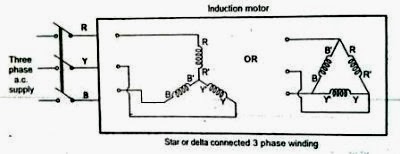
    A three-phase induction motor consists of three phases winding as its stationary part called stator. The three-phase stator winding is connected in star or delta.

    The three-phase windings are displaced from each other by 120°. The windings are supplied by a balanced three phase ac supply.

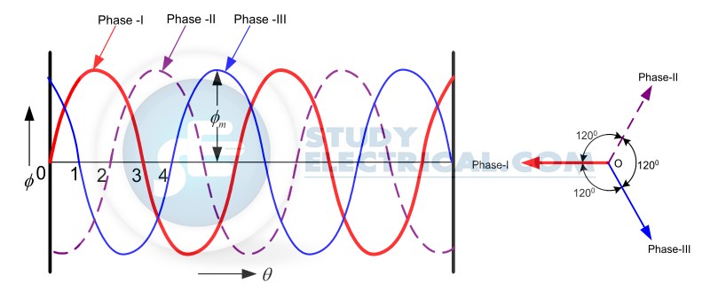
    The three-phase currents flow simultaneously through the windings and are displaced from each other by 120° electrical. Each alternating phase current produces its own flux which is sinusoidal.

    So all three fluxes are sinusoidal and are separated from each other by 120°.

    If the phase sequence of the windings is R-Y-B, then mathematical equations for the instantaneous values of the three fluxes ΦR , ΦY ,ΦB can be written as,
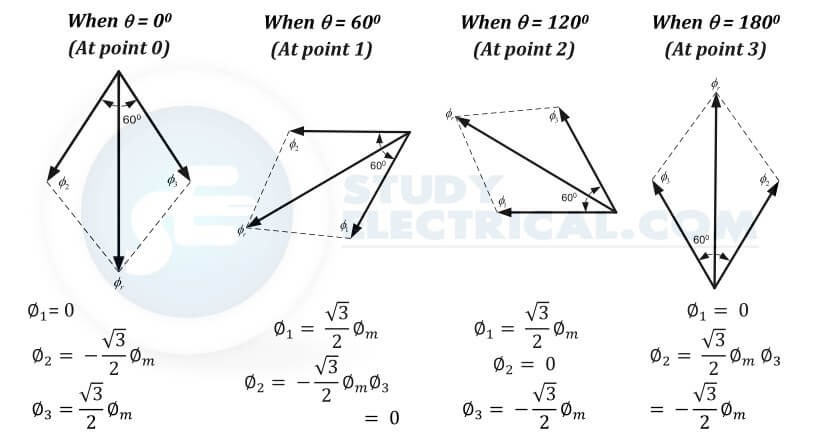
    ΦR =  Φmsin(ωt) 

    ΦY =  Φmsin(ωt – 120) 

    ΦB  =  Φmsin(ωt – 240)

    As windings are identical and supply is balanced, the magnitude of each flux is Φm .

    Phasor diagram of three phase
    Waveforms of three fluxes and their positive directions

    Table of Contents

      • Case 1 : ωt = 0
      • Case 2 : ωt = 60
      • Case 3 : ωt = 120
      • Case 4 : ωt = 180
    • Speed of Rotating Magnetic Field
    • Direction of Rotating Magnetic Field
      • Related Articles

    Case 1 : ωt = 0

    ΦR =  Φmsin(0) =  0

    ΦY =  Φmsin(0 – 120) =  -0.866 Φm

    ΦB  =  Φmsin(0 – 240) = +0.866 Φm

    Rotating magnetic field case 1
    Rotating magnetic field case 1

    Case 2 : ωt = 60

    ΦR =  Φmsin(60) =  +0.866 Φm

    ΦY =  Φmsin(- 60) =  -0.866 Φm

    ΦB  =  Φmsin(- 180) = 0

    Rotating magnetic field case 2
    Rotating magnetic field case 2

    Case 3 : ωt = 120

    ΦR =  Φmsin(120) =  +0.866 Φm

    ΦY =  Φmsin(0) =  0

    ΦB  =  Φmsin(- 120) = -0.866 Φm

    Rotating magnetic field case 3
    Rotating magnetic field case 3

    Case 4 : ωt = 180

    ΦR =  Φmsin(180) =  0

    ΦY =  Φmsin(60) =  +.866 Φm

    ΦB  =  Φmsin(- 60) = -0.866 Φm

    Case 4 rotating magnetic field
    Case 4 rotating magnetic field
    Case 1 : ωt = 0

    ΦR =  Φmsin(0) =  0
    ΦY =  Φmsin(0 – 120) =  -0.866 Φm
    ΦB  =  Φmsin(0 – 240) = +0.866 Φm
    Case 2 : ωt = 60

    ΦR =  Φmsin(60) =  +0.866 Φm
    ΦY =  Φmsin(- 60) =  -0.866 Φm
    ΦB =  Φmsin(- 180) = 0
    Case 3 : ωt = 120

    ΦR =  Φmsin(120) =  +0.866 Φm
    ΦY =  Φmsin(0) =  0
    ΦB =  Φmsin(- 120) = -0.866 Φm
    Case 4 : ωt = 180

    ΦR =  Φmsin(180) =  0
    ΦY =  Φmsin(60) =  +.866 Φm
    ΦB =  Φmsin(- 60) = -0.866 Φm
    Rotating magnetic field magnitude at different angles
    Rotating-magnetic-field-magnitude (1)
    Rotating-magnetic-field-magnitude

    By comparing the electrical and phasor diagrams we can find the flux rotates one complete 360 degrees on the 180-degree displacement of flux.

    WP 20140123 17 27 33 Pro

    Speed of Rotating Magnetic Field

    The speed at which the rotating magnetic field revolves is called the synchronous speed (Ns).

    Referring to the waveform of three phases, the time instant 4 represents the completion of one quarter cycle of alternating current Ix from the time instant 1.

    During this one-quarter cycle, the field has rotated through 90°. At one complete cycle of current Ix from the origin, the field has completed one revolution.

    Therefore, for a 2-pole stator winding, the field makes one revolution in one cycle of current. In a 4-pole stator winding, it can be shown that the rotating field makes one revolution in two cycles of current.

    In general, for P poles, the rotating field makes one revolution in P/2 cycles of current.

    $\therefore$ Cycles of Current $=\frac{P}{2} \times$ revolutions of field.

    or Cycles of current per second $=\frac{P}{2} \times$ revolutions of field per second

    Since revolutions per second is equal to the revolutions per minute (Ns ) divided by 60 and the number of cycles per second is the frequency f,

    $f=\frac{P}{2} \times \frac{N_{S}}{60}=\frac{N_{S} P}{120}$

    $\therefore \quad N_{S}=\frac{120 f}{P}$

    The speed of the rotating magnetic field is the same as the speed of the alternator that is supplying power to the motor if the two have the same number of poles. Hence the magnetic flux is said to rotate at synchronous speed.

    Direction of Rotating Magnetic Field

    The phase sequence of the three-phase voltage applied to the stator winding in the first figure is R-Y-B.

    If this sequence is changed to R-B-Y, it is observed that the direction of rotation of the field is reversed i.e., the field rotates counterclockwise rather than clockwise.

    However, the number of poles and the speed at which the magnetic field rotates remain unchanged.

    Thus it is necessary only to change the phase sequence in order to change the direction of rotation of the magnetic field. For a three-phase supply, this can be done by interchanging any two of the three lines.

    As we shall see, the rotor in a 3-phase induction motor runs in the same direction as the rotating magnetic field.

    Therefore, the direction of rotation of a 3-phase induction motor can be reversed by interchanging any two of the three motor supply lines.

    Related Articles

    • video how single phase motor works
      Video - How Single Phase Induction Motor Works?

      Read about working of induction motors here. All topics under single phase induction motor are…

    • Split Phase Induction Motor
      Split Phase Induction Motor - Operation and Characteristics

      Before going to the operation and characteristics of split-phase induction motor we should first understand…

    • Induction Motor and Transformer
      Comparison between Induction Motor and Transformer

      An induction motor may be considered to be a transformer with a rotating short-circuited secondary.…

    • single-phase-Induction
      Single Phase Induction Motor - Working Principle and Construction

      Single-phase motors are the most familiar of all-electric motors because they are extensively used in…

    • Stepper motor types
      Types of Stepper Motor

      A stepper motor is an electromechanical device which converts electrical pulses into discrete mechanical movements. …

    • Capacitor-start-induction-run
      Capacitor Start Single Phase Induction Motor - Working and Characteristics

      The capacitor start single phase induction motor is a type of split-phase induction motor. Capacitors…

    • Share:
    author avatar
    Electrical Engineer

    Previous post

    Objective Questions on Alternators | Part 4
    January 23, 2014

    Next post

    AC Single Phase Motors
    February 8, 2014

    You may also like

    transformer-winding
    Transformer Windings: Types and Design
    22 November, 2022
    Photo by Sven Daniel on Unsplash
    What is CNC Machining? | Definition, Processes, Components & More
    3 November, 2022
    Generator on Load
    DC Generator Problems and Solution: EMF Equation of DC Generator
    27 September, 2022

      4 Comments

    1. Anne
      December 19, 2018
      Reply

      Not sufficient content.please do explain. the direction of fields due to 3 windings.Thank you!

      • Tesla Edison
        admin
        December 19, 2018
        Reply

        Thank you Anne for your suggestion. We will update the article shortly.

    2. Abisharma
      January 13, 2019
      Reply

      is thia sufficent for exams

    Leave A Reply Cancel reply

    Your email address will not be published. Required fields are marked *

    Search Here

    From Blog

    impact of not calibrating your equipment
    The 5 Rules for Instrument Calibration
    01Nov2022
    SF6 Circuit Breaker
    Methods of Arc Extinction in Circuit Breaker
    23May2014
    capacitor charging and discharging
    Charging and Discharging a Capacitor
    29Feb2020
    Types of Power plants
    Types of Power Plants
    28Jul2015

    Categories

    • Alternator
    • Arduino
    • Basic Electrical
    • Battery
    • Books
    • Cables
    • Capacitor
    • Career
    • Circuit Breaker
    • Control System
    • DC Generator
    • DC Generator MCQ
    • DC Generator Solved Problems
    • DC Motor
    • DC Motor MCQ
    • Drives
    • Electric Vehicles
    • Electrical Circuits
    • Electrical Machines
    • Electrical Relays
    • Electrical Safety
    • Electronics
    • Embedded System
    • Exams
    • Generation
    • Guest Post
    • HVDC
    • Instrumentation
    • Interview Questions
    • Locomotives
    • MCQ
    • Measurement
    • Microcontroller
    • Objective Questions
    • PCB
    • PLC
    • Power System
    • Problems and Solution
    • Projects
    • Resistor
    • Signals and Systems
    • Single Phase Motors
    • Substation
    • Switchgear
    • Synchronous Motor
    • Three Phase Induction Motor
    • Transformer
    • Transmission Line
    • Uncategorized

    Copyright © 2021 Study Electrical, Inc.

    © StudyElectrical.Com 2021

    Login with your site account

    Lost your password?