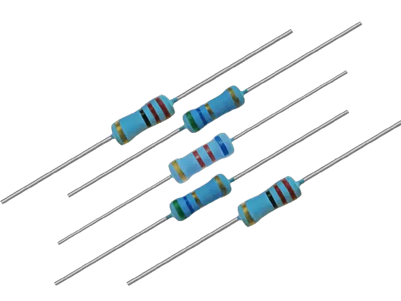
What is a Thin Film Resistor
A thin-film resistor is a resistor that employs a thin resistive layer. A ceramic base is positioned underneath this layer. This resistor has an extremely small thickness of only 0.1 microns compared to thick film resistors. These resistors are typically employed in higher precision technologies because they are more accurate, stable, and have a superior temperature coefficient. Although they appear to be identical, thick film and thin film resistors have different manufacturing processes.
Properties of thin-film resistors
- The resistance Value ranges from 0.2 – 20 MΩ.
- Tolerance ranges from ±0.1 to ±2 %.
- The temperature Coefficient is from ±5 to ±50 ppm/°C.
- The maximum operating temperature is 155°C.
- Maximum Operating Voltage is 50 to 500V.
- Non-linearity is >110dB.
- The current Noise is less than 0.1 µV/V.
- Power Rating is 1/16 to 1 W.
- Stability is ±0.15 to ±0.5 ∆R/R %.
- High-frequency behavior.
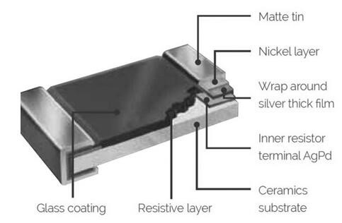
Construction of a Thin Film Resistor
Through the sputtering of the resistive material over the ceramic, the film resistor can be built. The surface can then be etched using the necessary etching procedures and ultraviolet exposure. This resistor is made of a variety of materials, including tantalum nitride, lead oxide, nickel-chromium, and ruthenium oxide. After that, lasers can be used to trim the etched film.
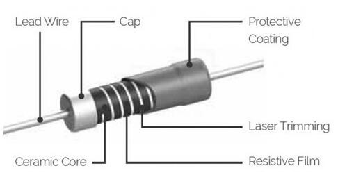
The resistance is determined by the film’s width, although if necessary, this can be changed through laser trimming. However, the concept is the same even if the resultant components are typically referred to as metal film resistors rather than thin film, at the expense of parasitic inductance. On the other hand, the film can be sputtered on a cylindrical face through axial leads.
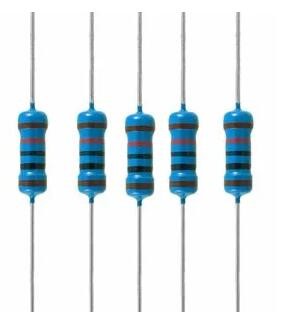
What is a Thick Film Resistor
A thick film resistive layer covering a ceramic base distinguishes this type of resistor from others. Although this resistor looks similar to a thin-film resistor, their manufacturing processes and physical characteristics are different. The thick film resistor is 1000 times thicker than the thin film resistor in terms of thickness. If you are interested in thin film resistor or think film resistor, you can look at the Electronic Part to see more products information and specifications about them.
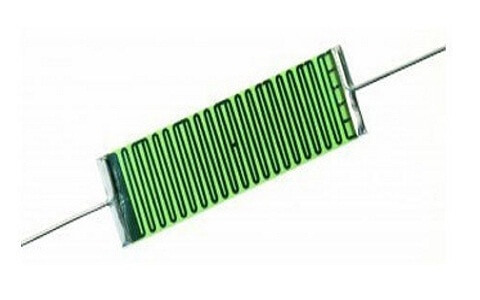
Construction of a Thick Film Resistor
An insulating substrate can be covered with conductive paste using a silk-screening technique to create a thick film resistor. To create a lasting connection, this conductive paste can be burned. A resistor element made of inorganic ceramics, glass frit, and silver are all present in the paste in finely divided form. A ceramic base comprised of aluminum oxide powder, glass frit, and a tiny amount of an organic binder to hold the powder together during fire is covered with the paste.
These resistors are inexpensive in large quantities and are accessible in small sizes. This is important in integrated and hybrid circuits since these resistors may be printed into the substrate, doing away with the need for board loading and soldering.
These resistors are entirely non-magnetic and can withstand temperatures up to 300°C. Therefore, these are employed in MRI and CT scanners and other places with intense magnetic fields. Thick film resistor versions without nickel or tin are suitable for lead-free soldering or silver epoxy attachment. All of these resistors exhibit low voltage coefficients of resistance, which is a feature that may be characterized as the variation in resistance with regard to the applied voltage throughout a particular range of voltage. The largest resistance levels, up to 10 tera ohms, as well as performance at extremely high temperatures are offered by thick film resistors.
Thin Film Resistor Vs Thick Film Resistor
Based on the resistive layer utilized on the base or ceramic substrate, thin film and thick film resistors are differentiated. Although these two resistors appear to be identical, their manufacturing process and characteristics have been altered. The names of these resistors can be traced back to the resistor’s layer thickness. The following characteristics distinguish a thin-film resistor from a thick-film resistor.
| Thin Film Resistor | Thick Film Resistor |
| This resistor is made by depositing a homogeneous, dense layer of a metallic alloy onto a ceramic substrate while it is under vacuum. Therefore, this layer functions as the resistive layer. | This resistor can be made by firing a paste into the substrate during the production process. In this case, glass and metal oxides make up the paste. |
| The price of manufacture is high. | The price of manufacture is not high. |
| It has a lower capacitance. | It has a greater capacitance. |
| This resistor’s tolerance is lower. | The tolerance of these resistors is higher. |
| The temperature coefficient is smaller in the thin-film resistor. | There is a high-temperature coefficient in a thick film resistor. |
| On an insulating substrate, a metallic film is part of these resistors. | These resistors are made by applying a specific paste to the substrate and burning it, which contains a mixture of glass and metal oxides. |
| The resistive layer employed in this resistor has a thickness of 0.1 micrometer. | This resistor’s resistive layer is a thousand times thicker than other resistive layers. |
| This resistor uses a thin film as its resistance layer. | This resistor uses a thick film as its resistance layer. |
Ti/TiN Thin Film Resistor Stability and Reliability
According to tests on the thermal stability and dependability of Ti/TiN thin-film resistors, the thermal stability of the resistor at 350°C is exceptional. Electrical experiments reveal that the “Ti” layer has lower electrical resistance than the TiN layer. Additionally, thermal activation of the resistor’s primary breakdown mechanism via Joule heating is possible.
For the Ti layer failure and the TiN layer failure, the activation of thermal energy can be calculated to be 1.3 eV and 1.8 eV, respectively. These findings suggest that if the temperature of Ti/TiN thin film resistors is kept below 311°C, they should remain electrically stable for at least 10 years.
In silicon microelectronic technology, coatings like titanium and titanium nitride are frequently utilized as diffusion barriers, anti-reflective layers, and adhesive layers. Additionally, these two films are useful in the production of thin-film resistors for MMICs and RFICs (radio frequency integrated circuits) (monolithic microwave integrated circuits). The TCR, or temperature coefficient of resistance, thermal stability, reliability performance, and specific resistivity are the key thin film resistor properties.
Tantalum nitride and titanium nitride have both been researched by engineers as potential thin-film resistors. However, there haven’t been many examinations into the dependability of these resistors that are used in semiconductor circuits. Additionally, because the first “Ti” layer serves as a wetting layer during the manufacturing of resistors, it is deposited before the TiN layer. The stability & reliability investigation characteristics for the Ti/TiN loaded thin film resistors are constrained.
Advantages and Disadvantages of a thin-film resistor
Advantages of Thin Film Resistor
- These resistors achieve much less resistor temperature coefficients & tolerances.
- They have less noise, lower capacitance & lower parasitic inductance.
- The electrical performance of these resistors is high.
- High-frequency response.
- It provides a high power rating.
- It has less noise.
- These resistors can be trimmed for accuracy.
Disadvantages of a thin-film resistor
- These components are delicate.
- High cost.
- Need to handle very carefully.
Applications of thin-film resistors
A thin-film resistor’s purpose is to be used in applications that need high accuracy, little noise, and great stability. Different tools like measurement, test, medical, monitoring, instrumentation, precision, and audio applications may be included in these applications. Precision applications use these resistors.
Other uses for these resistors include stable voltage division, stable references, ADC or DAC, and stable feedback loops. They are also used to adjust the gain of op-amps. These resistors in a network form offer added performance advantages.
Wherever higher accuracy is required, such as in equipment monitoring and measuring in the aerospace and medical industries, audio computer chips, RF applications, telecommunications, power supply converters, HVAC systems, etc., thin-film resistors are utilized.