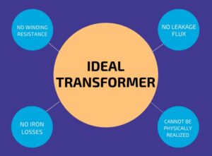
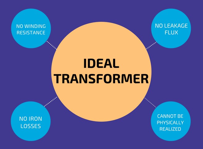
Ideal Transformer
- no winding resistance
- no leakage flux i.e., the same flux links both the windings
- no iron losses (i.e., eddy current and hysteresis losses) in the core
Ideal Transformer

Consider an ideal transformer on no load i.e., the secondary is open-circuited as shown in the figure. Under such conditions, the primary is simply a coil of pure inductance.
When an alternating voltage V₁ is applied to the primary, it draws a small magnetizing current Iₘ which lags behind the applied voltage by 90°. This alternating current Iₘ produces an alternating flux ϕ which is proportional to and in phase with it.
The alternating flux ϕ links both the windings and induces e.m.f. E₁ in the primary and e.m.f. E₂ in the secondary. The primary e.m.f. E₁ is, at every instant, equal to and in opposition to V₁ (Lenz’s law). Both e.m.f.s E₁, and E₂ lag behind flux ϕ by 90°. However, their magnitudes depend upon the number of primary and secondary turns.
Phasor Diagram of Ideal Transformer
The phasor diagram of an ideal transformer on no load is also shown above. Since flux ϕ is common to both the windings, it has been taken as the reference phasor.
The primary e.m.f. E₁ and secondary e.m.f. E₂ lag behind the flux ϕ by 90°.
Note that E₁ and E₂ are in phase. But E₁ is equal to V₁ and 180° out of phase with it.
Practical Transformer
- iron losses,
- winding resistances and,
- magnetic leakage, giving rise to leakage reactance.
1. Iron Losses
Since the iron core is subjected to alternating flux, there occurs eddy current and hysteresis loss in it. These two losses together are known as iron losses or core losses.
The iron losses depend upon the supply frequency, the maximum flux density in the core, volume of the core, etc.
It may be noted that the magnitude of iron losses is quite small in a practical transformer.
2. Winding resistances
Since the windings consist of copper conductors, it immediately follows that both primary and secondary will have winding resistance. The primary resistance R₁ and secondary resistance R₂ act in series with the respective windings as shown in the figure.
When current flows through the windings, there will be power loss as well as a loss in voltage due to IR drop. This will affect the power factor and E₁ will be less than V₁ while V₂ will be less than E₂.
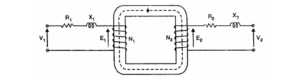
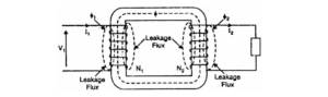
3. Leakage reactances
Both primary and secondary currents produce flux. The flux ϕ which links both the windings is the useful flux and is called mutual flux.
However, the primary current would produce some flux ϕ which would not link the secondary winding. Similarly, the secondary current would produce some flux ϕ that would not link the primary winding.
The flux such as ϕ₁ or ϕ₂ which links only one winding is called leakage flux. The leakage flux paths are mainly through the air. The effect of these leakage fluxes would be the same as though inductive reactance were connected in series with each winding of the transformer that had no leakage flux as shown in the figure.
In other words, the effect of primary leakage flux ϕ₁ is to introduce an inductive reactance X₁ in series with the primary winding as shown. Similarly, the secondary leakage flux ϕ₂ introduces an inductive reactance X₂ in series with the secondary winding.
There will be no power loss due to leakage reactance. However, the presence of leakage reactance in the windings changes the power factor as well as there is voltage loss due to IX drop.
Note.
Although leakage flux in a transformer is quite small (about 5% of ϕ) compared to the mutual flux ϕ, yet it cannot be ignored.
It is because leakage flux paths are through the air of high reluctance and hence require considerable e.m.f. It may be noted that energy is conveyed from the primary winding to the secondary winding by mutual flux f which links both the windings.
Comments are closed.