This set of DC Generator Problems with Solution focuses on problems based on EMF equation of DC Generator.
DC Generator Problem 1
A four-pole generator, having wave-wound armature winding has 51 slots, each slot containing 20 conductors. What will be the voltage generated in the machine when driven at 1500 rpm assuming the flux per pole to be 7.0 mWb ?
Solution:
From the emf equation of DC generator,
$E_g=\frac{\Phi Z N}{60}\left(\frac{P}{A}\right)$ volts
Here, Φ = 7 × 10⁻³ Wb,
Z = 51 × 20 = 1020,
P = 4, A = 2
N = 1500 r.p.m.
$\therefore \quad E_g=\frac{7 \times 10^{-3} \times 1020 \times 1500}{60}\left(\frac{4}{2}\right)=357 \mathrm{~V}$
DC Generator Problem 2
An 8-pole d.c. generator has 500 armature conductors, and a useful flux of 0.05 Wb per pole. What will be the e.m.f. generated if it is lap-connected and runs at 1200 rpm ? What must be the speed at which it is to be driven produce the same e.m.f. if it is wave-wound?
Solution:
With lap-winding,
P = a = 8
E = φ (N/60) (P/a)
= 0.05 × 500 × 20 × 1,
= 500 volts
Emf generated is 500 V for lap winding.
If it is wave-wound,
P = 8, a = 2, P/a = 4
and E = 0.05 × 500 × (N/60) × 4
For E = 500 volts, N = 300 rpm
Hence, with wave-winding, it must be driven at 300 rpm to generate 500 volts.
Additional Explanation:
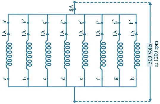
Assume 1 amp as the current per conductor.
Lap-wound, 1200 rpm :
500 V per coil-group, 8 groups in parallel
Net output current = 8 amp
Power output = 4 kW
Wave-wound, 300 rpm :
2 groups in parallel, one group has four coils in series, as shown below.
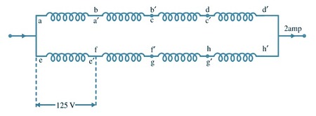
Total power-output is now 500 × 2 = 1000 W.
It is reduced to one fourth, being proportional to the speed.
DC Generator Problem 3
A DC shunt generator has an induced voltage on open-circuit of 127 volts. When the machine is on load, the terminal voltage is 120 volts. Find the load current if the field circuit resistance is 15 ohms and the armature-resistance is 0.02 ohm. Ignore armature reaction.
Solution:
Generator on no load :
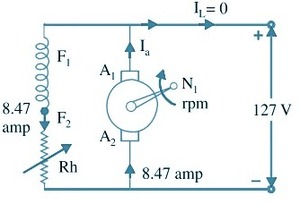
As shown in the figure of generator on no load, the machine is run at N1 rpm.
Eg = 127 + 8.47 × 0.02 = 127.17 volts
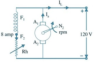
The above figure shows the loaded generator running at speed N2
From Figure, if = 8 amp
Eg can be 127.17 volts, if the speed is increased to N2 rpm, such that
$8.47 N_1=8 N_2$, or $N_2=\frac{8.47}{8} N_1=1.05875 N_1$
Thus the effect due to 5.875% decrease in flux is compensated by 5.875% increase in speed.
If Eg is assumed to remain unaltered at 127.17 V,
$I_a=\frac{127.17-120}{0.02}=358.5 \mathrm{amp}$
Hence, IL = 358.5 – 8 = 350.5 amp.
DC Generator Problem 4
An 8-pole d.c. shunt generator with 778 wave-connected armature conductors and running at 500 r.p.m. supplies a load of 12.5 Ω resistance at terminal voltage of 50 V. The armature resistance is 0.24 Ω and the field resistance is 250 Ω. Find the armature current, the induced e.m.f. and the flux per pole.
Solution:
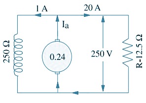
Load current = V/R = 250/12.5 = 20 A
Shunt current = 250/250 = 1 A
Armature current = 20 + 1 = 21 A
Induced e.m.f. = 250 + (21 × 0.24) = 255.04 V
Now, $\quad E_g=\frac{\Phi Z N}{60} \times\left(\frac{P}{A}\right)$
$$
\therefore \quad 255.04=\frac{\Phi \times 778 \times 500}{60}\left(\frac{8}{2}\right)
$$
Φ = 9.83 mWb
DC Generator Problem 5
In a 120 V compound generator, the resistances of the armature, shunt and series windings are 0.06 Ω, 25 Ω and 0.04 Ω respectively. The load current is 100 A at 120 V. Find the induced e.m.f. and the armature current when the machine is connected as (i) long-shunt and as (ii) short-shunt. How will the ampere-turns of the series field be changed in (i) if a diverter of 0.1 ohm be connected in parallel with the series winding ? Neglect brush contact drop and ignore armature reaction.
Solution:
(i) Long Shunt [Fig a]
Ish = 120/125 = 4.8 A ; I = 100 A ; Ia = 104.8 A
Voltage drop in series winding = 104.8 × 0.04 = 4.19 V
Armature voltage drop = 104.8 × 0.06 = 6.29 V
∴ Eg = 120 + 3.19 + 6.29 = 130.5 V

(ii) Short Shunt [Fig c]
Voltage drop in series winding = 100 × 0.04 = 4 V
Voltage across shunt winding = 120 + 4 = 124 V
∴ Ish = 124/25 = 5 A ; ∴ Ia = 100 + 5 = 105 A
Armature voltage drop = 105 × 0.06 = 6.3 V
Eg = 120 + 5 + 4 = 129 V
When a diverter of 0.1 Ω is connected in parallel with the series winding, the diagram becomes as shown in Fig (b). As per current-divider rule, the current through the series winding is = 104.8 × 0.1/(0.1 + 0.04) = 74.86 A. It means that the series field current has decreased from an original value of 104.8 A to 74.86 A.
Since No. of turns in the series winding remains the same, the change in series field ampere-turns would be the same as the change in the field current. Hence, the percentage decrease in the series field ampere-turns = (74.86 − 104.8) × 100/104.8 = −28.6%.
Comments are closed.