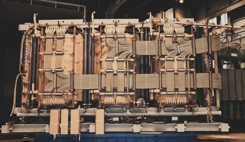
Transformer windings are one of the most important parts of a transformer. There are different types of transformer windings available on the market. The selection of transformer windings is based on different factors such as voltage, current and capacity of the transformer under construction.
Transformer Winding Requirements
The selected transformer winding must comply with a number of requirements. Here are a few of the most important:
- Windings should be economical both in terms of initial cost, taking into consideration the availability of copper on the market, and in terms of the efficiency of the transformer.
- Transformer windings must meet certain temperature requirements, as deviation from these conditions will drastically shorten the transformer’s service life.
- Windings should be mechanically stable with respect to the forces resulting from sudden short circuits in transformers.
- Electrical strength of the winding should be adequate to withstand overvoltages.
In many cases, these requirements contradict one another. For example, higher current density in the winding means less copper is needed, but copper losses increase, which decreases transformer efficiency. Allowing a greater temperature rise in the winding results in a smaller transformer, but a shorter service life. Electrical engineer Rick Brandt emphasizes that it is extremely important to design the winding of a modern transformer, especially in the case of a high-voltage transformer.
Transformer Winding Design
The high voltage and low voltage windings of a transformer are designed and selected in such a way that the axial short-circuit force is as low as possible, allowing coil support to be much simpler.
Material Used
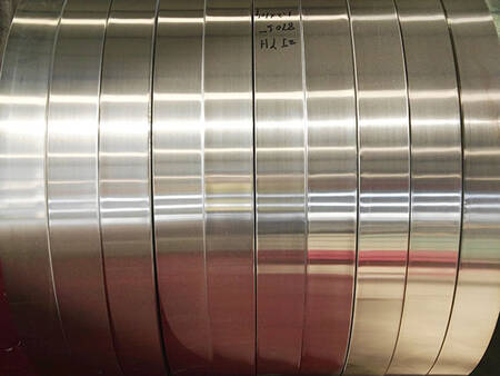
Copper and aluminum are the primary materials used as conductors in power transformer windings.
To carry current with similar performance to copper, aluminum conductors must have a larger cross section. Aluminum is lighter and generally less expensive than copper.
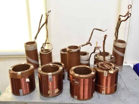
Copper conductors have a higher mechanical strength and are almost exclusively used except for smaller size ranges, where aluminum conductors would be acceptable.
In cases where extreme forces are encountered, materials such as silver-bearing copper can be used for even greater strength.
Here is a chart on comparison of properties of copper and aluminum.
| Property | Unit | Copper | Aluminium |
|---|---|---|---|
| Resistivity at 20°C | Ω mm2 / m | 0,0175 | 0,0285 |
| Electrical conductivity at 20°C | m / Ω mm2 | 57,1 | 35,4 |
| Temperature Coefficient of electrical resistance at 20°C | – | 0,00427 | 0,0044 |
| Thermal conductivity | W / m °C | 393 | 203 |
| Specific heat | W sec / kg °C | 385 | 920 |
| Melting point | °C | 1084 | 658 |
| Boiling point | °C | 2595 | 2060 |
| Specific weight | kg / m3 | 8900 | 2700 |
| Tensile strength | kgf / mm2 | 24 | 10 |
| Elastic limit | kgf / mm2 | 6 – 8 | 2 – 5 |
| Coefficient of linear expansion at 20°C | – | 17 x 10-6 | 24 x 10-6 |
Transposition of Conductors in Transformer
As discussed above the conductors used in transformer windings are either solid or stranded copper or aluminum strips. Heavy current capacity is achieved with conductors of large cross-section. It is preferable to use several small wires or parallel straps instead of one large strap to reduce eddy current losses in the conductors. As a result, the conductor components have unequal reactance, which can be eliminated by transposing the conductors.
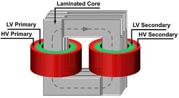
A transposition of conductors in a transformer involves winding one-half of each winding on each limb instead of placing the primary on one and the secondary on the other. By doing this, a tight coupling is guaranteed between the two windings. Consequently leakage flux is considerably reduced.
Positioning of HV and LV Windings
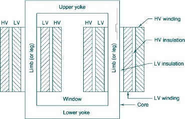
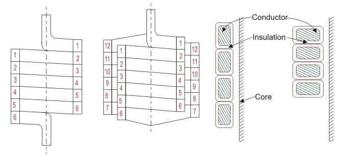
The position of HV and LV windings with respect to the core also plays a very critical role in terms of insulation requirements.
If the HV winding were placed next to the core, it would be necessary to insulate it from both the core and the LV winding. In addition, two layers of HV insulation would be required.
When the high-voltage winding is placed outside and around the low-voltage winding, only one layer of high-voltage insulation is necessary.
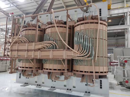
Transformer Winding Assembly
Transformer winding coils are almost always wound onto forms, dipped in insulating varnish, baked into a rigid mass, and then assembled with the core. The coils are most economical to wind on rectangular forms since it is easiest to build the core with rectangular legs.
In small transformers, rectangular concentric coils are a practical choice. Large transformers, however, tend to round out the flat sides of the outer coil due to the strong repulsion forces generated between the primary and secondary coils under short-circuit conditions. As a result, the transformer will usually be unserviceable if the coil insulation is damaged. In order to solve this mechanical strength problem, cylindrical concentric coils are the obvious solution.
Concentric and Sandwich Windings
It is possible to arrange high and low voltage windings in either a concentric or sandwich arrangement. Each winding in the concentric arrangement has a common center, forming circles in each cross-section. In sandwich windings, the high voltage and low voltage windings alternate along the leg height.
Concentric windings are employed in core type transformers whereas sandwich windings are almost exclusively used in shell type transformers.
Because of the easier insulation, concentric windings place the low-voltage winding closer to the core, while sandwiched windings place it on the outside. The insulation spaces between low and high-voltage coils also serve to facilitate cooling.
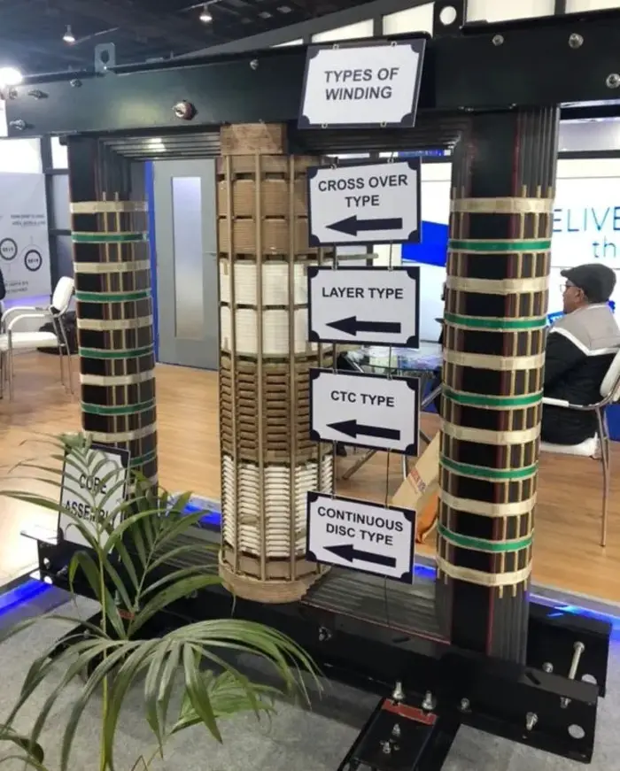
Types of Transformer Windings
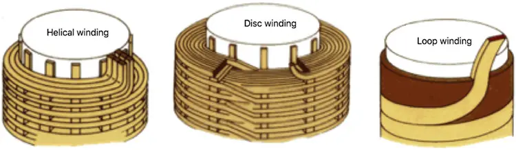
The concentric windings used for core types of transformers can further be classified in many groups. The most important transformer windings are
- Cylindrical winding
- Helical winding
- Cross-over winding
- Continuous disc winding.
Cylindrical Windings
Generally, cylindrical windings are layered in design and use rectangular (or strip) or round conductors. When the cross-section of a turn does not exceed 8 to 10 mm2, the cylindrical winding may be made of several layers of round conductors. In windings with a large cross section, rectangular (or strip) conductors are used, usually double-layered.
The figure shows a cylindrical winding with strip conductors. The winding is made up of turns helically wound round the cylinder generatix with the turns close to each other. Hence, the height of the winding is equal to the height of the layer. The rectangular conductor can be wound either flat or edgewise. In the former case, the larger size of the conductor is arranged in the axial direction whereas, in the latter case, it is arranged in the radial direction.
When the turn section (turn cross section) exceeds 40-45 mm2, a turn is made of several single conductors arranged along the height of the layer, so that they all occupy the same position relative to the leakage field. To improve cooling, ducts 5 to 8 mm wide are left between the winding layers (the greater figure refers to larger transformers).
Cylindrical windings with circular conductors are typically used for HV windings with voltages up to 6.6 kV, 11 kV, or 33 kV for ratings up to 600-1,000 kVA. Cylindrical windings with round conductors are mainly employed for low voltage windings up to 6.6 kV for ratings up to 600-750 kVA.
Helical Windings
A helical winding is used for LV coils in medium and high capacity transformers, where the number of coil turns is small but the current is high (up to 2,000 A). Therefore, low voltage windings of medium and high capacity transformers, require the use of a conductor consisting of a row of parallel rectangular conductors arranged in one radial direction of the winding flatwise and close to each other.
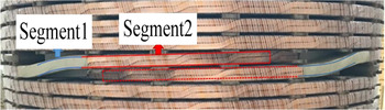
For a more uniform distribution of current between the parallel conductors, they are transposed so that each conductor may take each position.
The number of parallel conductors in the turn of a helical winding usually varies from 6 to 20. In essence, helical windings are similar to cylindrical windings, except there are axial spacers provided between adjacent turns in helical windings in order to improve oil circulation and improve cooling as a result of better oil circulation. The ducts are formed by spacers placed regularly around the periphery of the cylinder. A continuous helical winding exhibits high axial mechanical strength and is often used for the LV windings of large power transformers.
A helical transformer winding is used in power transformers ranging from 150 kVA to 30 MVA at voltages between 400 V and 11 kV and sometimes up to 33 kV.
Crossover Windings
Crossover windings are suitable for currents not exceeding 20 A. They are widely used for high voltage windings of low rating transformers. This is because such transformers may have a large number of turns but the conductors have a small circular section with double cotton or paper coverings.
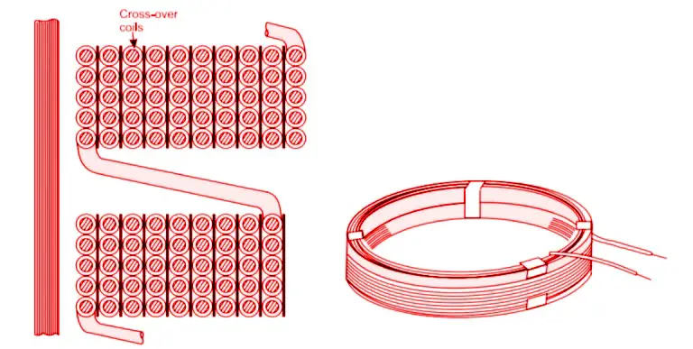
Depending on the voltage rating, the entire winding may be divided into multiple coils. The coils are wound on formers, usually U-shaped ones, with several layers of several turns per layer. The coil ends, one from inside and one from outside, are joined to other similar coils in series. These coils are spaced with blocks of insulating material to allow free circulation of oil. The axial length of each coil and the separation distance between each coil vary according to the voltage rating.
A cross-over winding may be employed in the same rating range as a cylindrical winding. A cross-over winding is stronger than a cylindrical winding under normal operating conditions. The disadvantages of this winding are its lower impulse strength and labour-intensive nature.
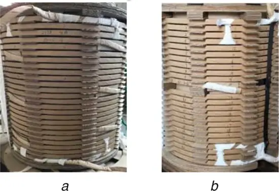
Continuous Disc Windings
Continuous disc windings, as their name suggests, consist of a number of flat coils or discs connected in series or parallel. The coils are formed with rectangular strips wound spirally from the centre outwards in the radial direction, as illustrated in figure.
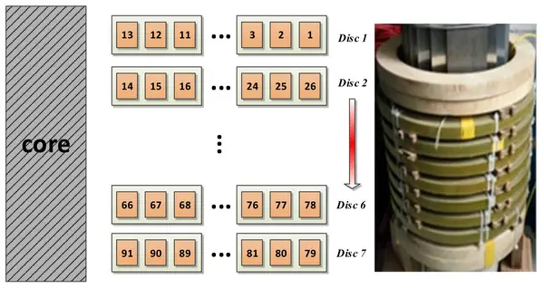
Conductors are used in lengths that are sufficient for complete winding or a section of winding between tappings. The conductor can be a single strip or number of strips in parallel, wound on the flat side. This gives a robust construction for each of the discs. Discs are wound on an insulating cylinder separated by strips along its length. The discs are separated from each other with pressboard sectors attached to vertical strips. The vertical and horizontal spacers provide radial and axial ducts for free circulation of oil which comes in contact with every turn. If a winding turn contains several parallel conductors, transposition of them is used as in the case of a helical winding.
Continuous disc windings are reliable and strong and, therefore, they are widely employed both as LV and HV windings in large rating transformers. When the continuous winding is used as a HV winding, tappings are made for regulation of the voltage ratio in the range of ± 5% or 2 (±2.5%).
Sandwich Windings
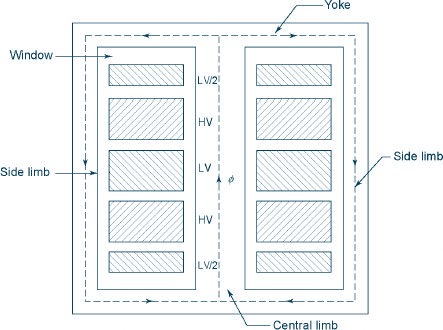
Sandwich windings are most commonly employed in shell type transformers and allow easy control of leakage reactance. Leakage reactance can be reduced by subdividing the low-voltage and high-voltage windings into a large number of sections or coils and arranging alternately the HV and LV sections with the LV section nearer to the yoke.
The two low voltage coils at the ends have half the turns of a normal low voltage coil. In order to balance the mmf of the adjacent sections, each normal section, whether hv or Iv, carries the same number of ampere turns. The larger the number of sections (or coils), the smaller is the leakage reactance. Coil sectionalization not only assists in controlling leakage reactance, but also improves cooling and handling.
Drawbacks of Sandwich Winding
In comparison to concentric windings they have several draw-backs:
- they are more labour-consuming in manufacture,
- less stable in respect to short-circuits and are
- more difficult to insulate from each other and from the yoke.
This is the reason why the core type transformers with concentric windings are more common.
Video
Related posts:
 Percentage Impedance of Transformer and Its Calculation
 Why Transformers are Rated in kVA, Not in kW? (With Proof)
 Transformer Bushing Types : RIP Bushing vs OIP Bushing
 How to Test Percentage Impedance of Transformer?
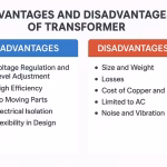 Advantages and Disadvantages of Transformers
 Delta-Delta (Δ–Δ) Transformer Connection: Advantages, Working, and Application
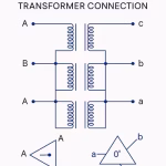
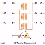 Three-Phase Transformer Connections: Y–Y, Δ–Δ, Y–Δ, Δ–Y, V–V, T-T
 Amplidyne – Working and Application
 What is CNC Machining? | Definition, Processes, Components & More
 Magnetomotive Force (MMF) and Ampere-Turns with Solved Problems