Hydraulic pumps are mechanically driven and use a rotating output shaft to deliver pressure. We use them in various industrial, commercial, and agricultural applications.
Types of Hydraulic Pumps
There are many types of hydraulic pumps. Most common include gear pumps, screw pumps, rotary vane, and piston pumps. These pumps can be further classified by the type of fluid they transport (oil, water, or air) and whether they’re positive or variable displacement in nature.
1. Gear Pumps
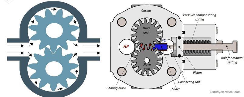
Gear pumps are the most common type of hydraulic pump. They use gears to transfer energy from one shaft to another. The direction of rotation is changed by changing the direction of the gear train. Gear pumps can be built with either spur gears or helical gears.
A typical gear pump consists of a housing containing two input shafts, one output shaft, and two gear trains (one between each shaft). The input shafts rotate at different speeds to produce a rotating output shaft. The gear trains are typically fixed-ratio gears; however, variable-speed gearing has been developed for some applications where this may be advantageous.
Because gear pumps require relatively few parts and are easy to manufacture, they were used for many years as the principal means of delivering hydraulic fluid under pressure.
2. Rotary Vane
Rotary vane pumps use a series of vanes to move oil from one end of the pump to another. This type of pump is often used for high-pressure applications because it has a high-pressure ratio and can handle a wide range of viscosities.
Rotary vane pumps are sometimes called rotary screw pumps because they use a screw-like shape to move oil through the pump. They have two major components: an outer casing and an inner casing. The inner casing contains multiple blades arranged around a central shaft, while the outer casing contains ports that allow oil to flow into the center of the pump and then out again.
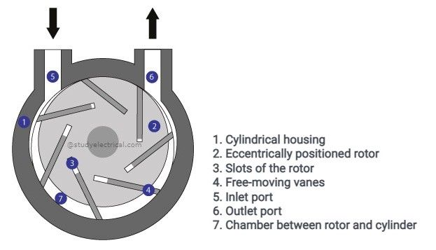
As this shaft turns, it moves these blades back and forth, causing them to rotate inside the outer casing’s ports. This, in turn, creates pressure within the chamber between each blade as it passes through its port, pushing oil through them until it reaches the other side of the chamber, where it exits through another port located at another location on the outer casing’s wall.
3. Piston Pumps
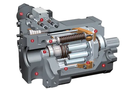
Piston pumps use fluid pressure to transfer energy from one place to another. The pressure required to start the pump and move fluid through it is called “prime.” The amount needed to stop the pump and hold it stationary is called “sustenance.”
The piston, or plunger, moves back and forth inside a cylinder to create pressure. Piston pumps work by compressing or expanding the volume of liquid inside the cylinder. As the piston moves up, it pushes down on the liquid inside and creates pressure. When it moves down, it draws in more liquid from below and expands the volume inside. This drives fluid out through an outlet port at the bottom of each stroke.
Pumps can be single-acting or double-acting; single-acting pumps use one side of the cylinder for suction and one side for discharge; double-acting pumps use both sides simultaneously for suction and discharge.
4. Screw Pumps
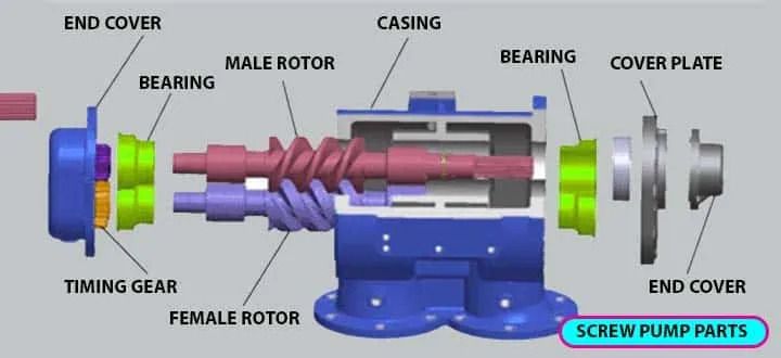
Screw pumps are the most common type of fluid pump. They are named for the way they move fluids. The pump has a long shaft with helical grooves cut into it. A rotating rod is attached to one end of the shaft. The liquid being pumped moves into these grooves and is pushed up by the centrifugal force as an electric motor or engine rotates the shaft.
Screw pumps are classified into two categories: single-stage and multi-stage. The main difference between these two types is that single-stage screw pumps have only one pumping chamber while multi-stage screw pumps have multiple ones.
i) Single Stage Screw Pump
A single-stage screw pump has only one pumping chamber, which can be either vertical or horizontal, depending on the application requirements. These pumps use a rotating helical shaft that moves up and down inside an enclosed tube called a cylinder or casing. The fluid enters at one end of the cylinder through an inlet port and exits out at another through an outlet port opposite to it after passing through all chambers along its path during rotation.
ii) Multi-stage Screw Pumps:
These pumps consist of multiple rotating threads that increase pressure within the system being operated by the pump. They are typically more expensive than single-stage screw pumps because they have more moving parts and require more maintenance than single-stage screw pumps; however, they can achieve higher pressures with less energy consumption due to their increased complexity.
A hydraulic pump is a necessary part of any hydraulic system. Without a pump, converting the energy from an electric motor into hydraulic power wouldn’t be possible. Pumps have some exceptional properties and are more efficient than any other method. Therefore, get your hydraulic dosing pumps in Saudia Arab from Ejawda,
Related posts:
 Percentage Impedance of Transformer and Its Calculation
 Why Transformers are Rated in kVA, Not in kW? (With Proof)
 Amplidyne – Working and Application
 Electrical Engineering Basics: The Ultimate Guide
 What’s The Advantage Of Eddy Current Testing
 Transformer Windings: Types and Design
 Critical Field Resistance of DC Shunt Generators
 Magnetomotive Force (MMF) and Ampere-Turns with Solved Problems
 Advantages and Disadvantages of Transformers
 Delta-Delta (Δ–Δ) Transformer Connection: Advantages, Working, and Application