DC motors are widely used in various applications, from robotics and industrial machinery to household appliances and automotive systems. One of the essential features of a DC motor is the ability to change its rotation direction. This capability allows for more versatile and flexible operation in different scenarios. In this article, we will explore the methods and techniques used to change the direction of a DC motor.
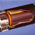
DC motors operation is based on the principle of electromagnetism. They consist of a stationary part, known as the stator, and a rotating part, called the rotor. The stator contains the field windings, which produce a magnetic field, while the rotor carries the armature windings that interact with the magnetic field to generate the motor’s rotation.
To change the direction of a DC motor, you need to alter the polarity of the applied voltage or current.
There are primarily two approaches to achieve this:
- using a mechanical switch
- employing an electronic circuit.
1. Using Mechanical Switch
The simplest way to change the direction of a DC motor is by using a mechanical switch, such as a toggle switch or a relay.
This method involves physically reversing the connections of either the field windings or the armature windings. By swapping the polarity of the voltage applied to the motor, the direction of rotation can be reversed.
This approach is commonly used in small-scale applications and hobby projects where simplicity is prioritized over automation.
2. Using Electronic Circuit
In more sophisticated applications, an electronic circuit is employed to change the direction of a DC motor. This method offers greater control and automation possibilities.
Here are two widely used electronic techniques:
- H-Bridge Circuit
- Motor Driver IC
H-Bridge Circuit
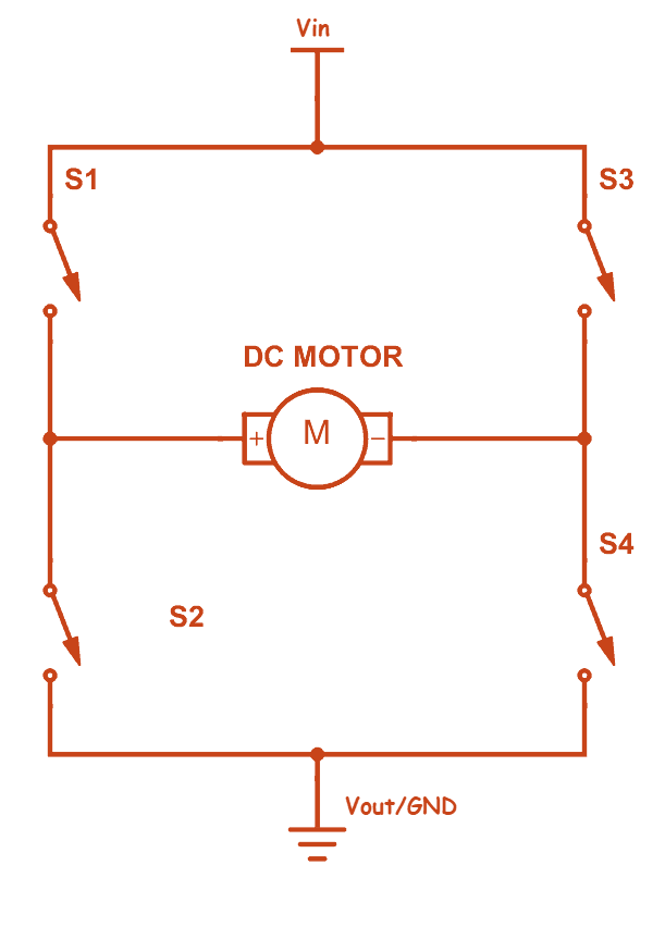
An H-bridge circuit is a common choice for controlling the direction of a DC motor.
It consists of four switches arranged in the shape of the letter “H.” The switches can be transistors or solid-state relays. By selectively turning on and off the switches, the polarity of the voltage across the motor can be reversed, thus changing its rotation direction.
H-bridge circuits provide precise control and can handle higher currents, making them suitable for a wide range of applications.
Motor Driver IC
Motor driver integrated circuits (ICs) offer a convenient way to control the direction and speed of a DC motor.
These ICs incorporate H-bridge circuitry along with additional features such as current sensing, speed control, and protection mechanisms.
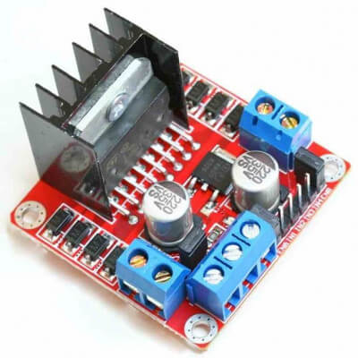
They are designed to be interfaced with microcontrollers or other control systems, allowing for programmable motor control. By providing the appropriate input signals to the motor driver IC, you can easily change the direction of the DC motor.
3. Reversing Polarity
Changing the direction of a DC motor essentially involves reversing the polarity of the applied voltage.
This polarity reversal causes the magnetic field produced by the field windings and the interaction between the field and armature windings to change, resulting in a reversal of the motor’s rotation direction.
4. Pulse Width Modulation (PWM):
PWM is a technique commonly used in electronic motor control to vary the speed and direction of a DC motor.
By rapidly switching the motor’s power on and off with a varying duty cycle, the average voltage and current delivered to the motor can be adjusted.
To change the direction, the PWM signal is inverted, effectively reversing the polarity during each switching cycle.
6. Controlling Direction with Microcontrollers:
Microcontrollers are commonly used to control DC motors in various applications. They provide the flexibility to program and automate the motor’s direction and speed changes.
By interfacing the microcontroller with appropriate motor control circuits or motor driver ICs, you can easily implement software-based control of the motor’s direction.
5. Brushed DC Motors vs. Brushless DC Motors:
There are two types of DC motors – Brushed DC motor and Brushless DC motor. The direction of rotation of these two types of dc motors is controlled by different methods.
The methods mentioned above apply primarily to brushed DC motors. Brushless DC (BLDC) motors, on the other hand, require a different approach to change their rotation direction. BLDC motors use electronic commutation instead of brushes and commutator, which means the switching of power phases needs to be controlled electronically to change the direction. This is typically achieved through specialized motor controller circuits.
Brushed DC Motor
Low Voltage DC motors
The small DC motors (which has 12V or below 12V) made up of permanent magnet i.e. it contains a permanent magnetic field. If we want to change the direction of the shaft we change the polarity only. Because it contains only armature winding only.
Another method is to use an H-bridge to control the direction of a DC motor. It is a special circuit which allows motor rotation in both directions. From four terminals of an H bridge, you can control the direction of a DC motor. The method is briefly explained in this article.
High Voltage DC motors
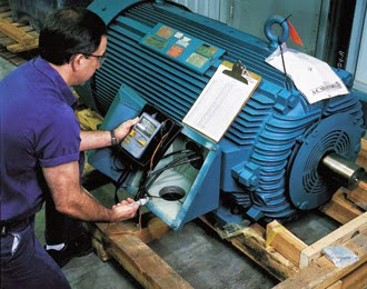
The high voltage DC motors (which has 220V or above 220V) made up of temporary magnet i.e. field and armature have separate winding. So if we change the polarity of the supply the total circuit will change. Due to that, the motor will rotate in normal direction.
If we want to change the direction of the shaft we need to change either field or armature supply. Take care, that you change either the field or the armature wires. If both are changed at the same time, the direction remains the same. Refer to the figure above.
Brushless DC Motor
For a 3-phase brushless DC motor – you’d need to change commutation order, this is slightly more complex because how to do that depends on what kind of position sensor is being used.
For hobby-type brushless motors, like the ones you’d find in an RC car or quadcopter, and other motors that use sensorless control for position detection, you can simply swap any two of the phase connections. You can also reprogram the motor driver controller (if such facilities exist).
For devices that use hall sensors or other low-resolution position sensors, you’d have to also switch one phase connection and a corresponding hall sensor. Alternatively, you can reprogram the motor driver controller.
For motors that use absolute position sensors like encoder wheels, you can only do this by reprogramming the motor driver controller.
For 3-phase brushless DC motors, if it tries to commutate in the wrong order, you can risk damaging the motor or the motor driver.
Using a Microcontroller
There are many things which you can do with your DC motor when interfaced with a micro-controller. For example, you can control the speed of motor, you can control the direction of rotation, you can also do encoding of the rotation made by DC motor i.e. keeping track of how many turns are made by your motors, etc. So you can see DC motors are no less than a stepper motor.
Usually, H-bridge has preferred the way of interfacing a DC motor. These days many IC manufacturers have H-bridge motor drivers available in the market like L293D is most used H-Bridge driver IC.
The name “H-Bridge” is derived from the actual shape of the switching circuit which control the motion of the motor. It is also known as “Full Bridge”. Basically there are four switching elements in the H-Bridge as shown in the figure below.
As you can see in the figure above there are four switching elements named as “High side left”, “High side right”, “Low side right”, “Low side left”. When these switches are turned on in pairs motor changes its direction accordingly. Like, if we switch on High side left and Low side right then motor rotate in the forward direction, as current flows from Power supply through the motor coil goes to ground via switch low side right. This is shown in the figure below.

| High Left | High Right | Low Left | Low Right | Description |
|---|---|---|---|---|
| On | Off | Off | On | Motor runs clockwise |
| Off | On | On | Off | Motor runs anti-clockwise |
| On | On | Off | Off | Motor stops or decelerates |
| Off | Off | On | On | Motor stops or decelerates |
H-bridge can be made with the help of transistors as well as MOSFETs, the only thing is the power handling capacity of the circuit. If motors are needed to run with the high current then a lot of dissipation is there. So head sinks are needed to cool the circuit.
Application Examples:
Discussing practical applications where changing the direction of a DC motor is crucial can help readers understand the importance of this functionality. For example, in robotic systems, changing the direction allows the robot to move forward, backward, or change its course. In conveyor systems, direction control determines the movement of materials. Mentioning specific examples can make the topic more relatable and showcase the real-world significance of reversing a DC motor’s direction.
Conclusion
Remember to provide clear instructions and precautions when working with DC motors, such as ensuring proper insulation, handling high currents safely, and avoiding short circuits. Understanding the principles and techniques for changing the direction of a DC motor empowers you to design and control systems that require versatile motor operation.

Comments are closed.