Many new electrical engineers are unaware of the use of sinusoids and phasors when they analyze AC circuits. In this article, we’ll explain how these can be used in analyzing AC circuits.
Sinusoids
Sinusoids are mathematical curves that describe smooth periodic oscillations. A sinusoid signal has the form of the sine or cosine function.
Sinusoidal currents are usually referred to as alternating currents (ac). Currents of this type reverse at regular intervals and alternate between positive and negative values. Circuits driven by sinusoidal voltage or current are referred to as AC circuits.
A sinusoidal forcing function produces both transient response and steady-state response, much like the step function. The transient response dies out with time so that only the steady-state response remains. When the transient response has become negligibly small compared with the steady-state response, we say that the circuit is operating at sinusoidal steady-state.
Why Sinusoids are used in AC Circuit Analysis?
It is common to use sinusoids and phasors to analyze AC circuits. So it is important to learn them.
The reasons behind the use of sinusoids in AC circuit analysis are,
- Almost all natural phenomena have sinusoidal characteristics.
- Signals in the sinusoidal form are simple to generate and transmit.
- Using Fourier analysis, any practical periodic signal can be represented as a sum of sinusoids.
- Mathematically, a sinusoid is easy to handle
Confused? don’t worry, I’ll explain each one to you.
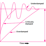
First, nature itself is characteristically sinusoidal. There is a sinusoidal variation in the motion of most natural phenomena. Some examples include the motion of a pendulum, the vibration of a string, the ripples on the ocean texture, and the natural response to underdamped second-order systems.
The video below shows motion of a pendulum creating sinusoidal waveform.
Second, a sinusoidal signal is easy to generate and transmit. A sinewave is the projection of a circle rotating at a constant speed along the time axis. It occurs everywhere in nature when something rotates, and is the most simple periodic function you can encounter.
Electrical generators rotate, so they produce voltage and current that is sinusoidal. That is their nature. It is the form of voltage generated throughout the world and supplied to homes, factories, laboratories, and so on. It is the dominant form of signal in the communications and electric power industries.
Third, through Fourier analysis, any practical periodic signal can be represented by a sum of sinusoids. You can express triangular and square wave in terms of fundamental sinusoidal frequency and its multiples according to Fourier series. Sinusoids, therefore, play an important role in the analysis of periodic signals.
Finally, sinusoids are simple to calculate mathematically. The derivative and integral of a sinusoid are also sinusoids.
For all the above reasons and other reasons, the sinusoid is an extremely important function in circuit analysis.
Sinusoids in Circuit Analysis
A sinusoidal forcing function produces both transient response and steady-state response, much like the step function.
The transient response dies out with time so that only the steady-state response remains. When the transient response has become negligibly small compared with the steady-state response, we say that the circuit is operating at sinusoidal steady-state.
Lets learn how sinusoids are used in circuit analysis.
For that, consider the sinusoidal voltage, 
Where,
Vm = the amplitude of the sinusoid
ω = the angular frequency in radians/s
ωt = the argument of the sinusoid
Period of a Sinusoid
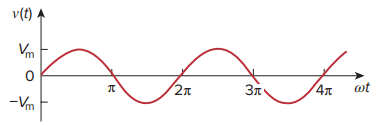
The figure shows the graphical representation of v(t) as a function of its argument ωt.
The sinusoid repeats itself every time T seconds, therefore T is called the period of the sinusoid.
From the plot above, we observe that
ωT = 2π
Hence, Time period of a sinusoid is,

Periodic Signal
A periodic function is one that satisfies  Periodic signal, for all t and for all integers n.
The fact that v(t) repeats itself every T seconds is shown by replacing t by (t + T) in ![]() .
.
Hence,

that is, v has the same value at t + T as it does at t and v(t) is said to be periodic.
Frequency of a Sinusoid
As mentioned, the period T of the periodic function is the time of one complete cycle or the number of seconds per cycle.
The reciprocal of this quantity is the number of cycles per second, known as the cyclic frequency of the sinusoid.

From the equations of time period and frequency, it is clear that, angular frequency,

While ω is in radians per second (rad/s), f is in hertz (Hz).
The unit of f is named after the German physicist Heinrich R. Hertz (1857–1894)
Phase and Argument
Let us now consider a more general expression for the sinusoid,
v(t) = Vm sin(ωt + ϕ)
where, ωt is the argument and ϕ is the phase.
Both argument and phase can be in radians or degrees.
Let us examine the two sinusoids, v1(t) = Vm sin ωt and v2(t) = Vm sin (ωt + ϕ)
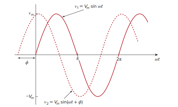
The starting point of v2 occurs first in time. Therefore, we say that v2 leads v1 by ϕ or that v1 lags v2 by ϕ.
If ϕ ≠ 0, we also say that v1 and v2 are out of phase. If ϕ = 0, then v1 and v2 are said to be in phase; they reach their minima and maxima at exactly the same time.
We can compare v1 and v2 in this manner because they operate at the same frequency; they do not need to have the same amplitude.
A sinusoid can be e xpressed in either sine or cosine form. When comparing two sinusoids, it is expedient to express both as either sine or cosine with positive amplitudes.
Some practice questions on sinusoids are given below.
-
Find the amplitude, phase, period, and frequency of the sinusoid.
v(t) = 12 cos(50t + 10°) VSolution:
The amplitude is Vm = 12 V.
The phase is ϕ = 10°.
The angular frequency is ω = 50 rad/s.
The period T = 2π/ω = 2π/50 = 0.1257 s.
The frequency is f = 1/T = 7.958 Hz. -
Calculate the phase angle between v1 = −10 cos(ωt + 50°) and v2 = 12 sin(ωt − 10°). State which sinusoid is leading.
Solution
We may regard v1 as simply −10 cosωt with a phase shift of +50°. Hence, v1 is as shown in figure.
Similarly, v2 is 12 sinωt with a phase shift of −10°, as shown in figure.
It is easy to see that v2 leads v1 by 30°, that is, 90° − 50° − 10°.
Phasors
A phasor is a complex number that represents the amplitude and phase of a sinusoid.
Sinusoids are easily expressed in terms of phasors, which are more convenient to work with than sine and cosine functions.
Phasor method in ac circuit analysis is introduced by Charles Proteus Steinmetz (1865–1923). He is a German-Austrian mathematician and engineer. He is also noted for his work on the theory of hysteresis.
Phasors provide a simple means of analyzing linear circuits excited by sinusoidal sources; solutions of such circuits would be intractable otherwise. The notion of solving ac circuits using phasors was first introduced by Charles Steinmetz in 1893.
Before we completely define phasors and apply them to circuit analysis, we assume that you are thoroughly familiar with complex numbers.
Basics of Complex Numbers
A complex number z can be written in rectangular form as
z = x + jy
where j = √−1 ; x is the real part of z; y is the imaginary part of z.
The complex number z can also be written in polar or exponential form as,

where r is the magnitude of z, and ϕ is the phase of z.
We notice that z can be represented in three ways:

The relationship between the rectangular form and the polar form is
shown in the graph below.
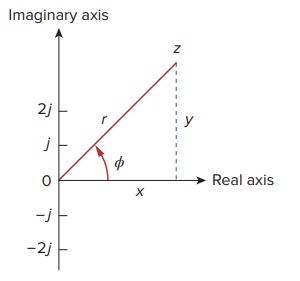
Given x and y, we can get r and ϕ as,
On the other hand, if we know r and ϕ, we can obtain x and y as,
Thus, z may be written as,
Phasor Representation
The idea of phasor representation is based on Euler’s identity. In general,
which shows that cos ϕ and sin ϕ as the real and imaginary parts of ejϕ.
Given a sinusoid v(t) = Vm cos(ωt + ϕ), we use above equation to express v(t) as,
V is thus the phasor representation of the sinusoid v(t).
In other words, a phasor is a complex representation of the magnitude and phase of a sinusoid.
A phasor may be regarded as a mathematical equivalent of a sinusoid with the time dependence dropped.
Consider the plot of the sinor Vejωt = Vmej(ωt+ϕ) on the complex plane.
As time increases, the sinor rotates on a circle of radius Vm at an angular velocity ω in the counterclockwise direction. We may regard v(t) as the projection of the sinor Vejωt on the real axis.
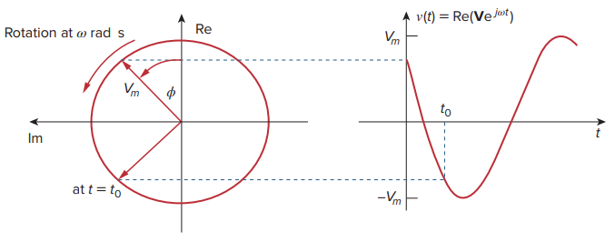
The value of the sinor at time t = 0 is the phasor V of the sinusoid v(t). The sinor may be regarded as a rotating phasor.
Thus, whenever a sinusoid is expressed as a phasor, the term ejωt is implicitly present. It is therefore important, when dealing with phasors, to keep in mind the frequency ω of the phasor; otherwise we can make serious mistakes.
Phasor Diagram
As a complex quantity, a phasor may be expressed in rectangular form, polar form, or exponential form. Because a phasor has magnitude and phase (“direction”), it behaves as a vector.
A graphical representation of phasors is known as a phasor diagram.
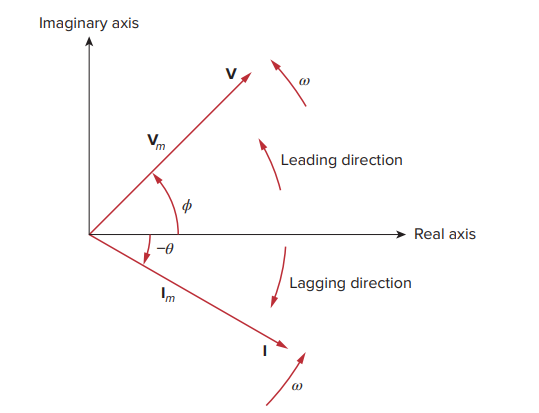
Phasor Domain and Time Domain
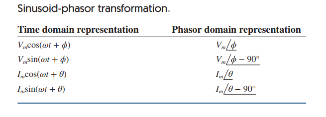
To get the phasor corresponding to a sinusoid, we first express the sinusoid in the cosine form so that the sinusoid can be written as the real part of a complex number.
Then we take out the time factor ejωt, and whatever is left is the phasor corresponding to the sinusoid.
By suppressing the time factor, we transform the sinusoid from the time domain to the phasor domain. This transformation is summarized as,
Given a sinusoid v(t) = Vm cos(ωt + ϕ), we obtain the corresponding phasor as V = Vm ∠ϕ.
In the last equation, the frequency (or time) factor ejωt is suppressed, and the frequency is not explicitly shown in the phasor domain representation because ω is constant.
However, the response depends on ω. For this reason, the phasor domain is also known as the frequency domain.
This shows that the derivative v(t) is transformed to the phasor domain as jωV.
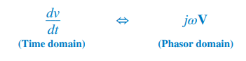
This allows the replacement of a derivative with respect to time with multiplication of jω in the phasor domain.
Similarly, the integral of v(t) is transformed to the phasor domain as V∕jω
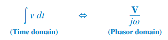
This allows the replacement of an integral with respect to time with division by jω in the phasor domain.
Both equations are useful in finding the steady-state solution, which does not require knowing the initial values of the variable involved. This is one of the important applications of phasors.
Besides time differentiation and integration, another important use of phasors is found in summing sinusoids of the same frequency.
Adding sinusoids of the same frequency is equivalent to adding their corresponding phasors.
The differences between v(t) and V should be emphasized:
- v(t) is the instantaneous or time domain representation, while V is the frequency or phasor domain representation.
- v(t) is time dependent, while V is not. (This fact is often forgotten by students.)
- v(t) is al ways real with no complex term, while V is generally complex.
Finally, we should bear in mind that phasor analysis applies only when frequency is constant; it applies in manipulating two or more sinusoidal signals only if they are of the same frequency.
Some practice problems on sinusoids and phasors are given below.
-
Transform these sinusoids to phasors:
(a) i = 6 cos(50t − 40°) A
(b) v = −4 sin(30t + 50°) VSolution:
(a) i = 6 cos(50t − 40°) has the phasor
I = 6∠−40° A(b) Since −sin A = cos(A + 90°),
v = −4 sin(30t + 50°) = 4 cos(30t + 50° + 90°)
= 4 cos(30t + 140°) V
The phasor form of v is
V = 4∠ 140° V -
Find the sinusoids represented by these phasors:
(a) I = −3 + j4 A
(b) V = j8e−j20° VSolution:
(a) I = −3 + j4 = 5∠ 126.87°. Transforming this to the time domain gives
i(t) = 5 cos(ωt + 126.87°) A(b) Because j = 1∠ 90°,
V = j8∠−20° = (1∠ 90°)(8∠−20°)
= 8∠⧸ 90° − 20° = 8∠ 70° V
Converting this to the time domain gives
v(t) = 8 cos(ωt + 70°)V
Related posts:
 Open Loop and Closed Loop Control System (4 Practical Examples Included)
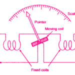 Electrodynamometer Instruments – Ammeter, Voltmeter and Wattmeter
 Damping Systems – Air friction, Fluid Friction & Eddy Current Damping
 Things You Should Know About Electromagnetic Flow Meters
 Digital Multimeter: Working and Application
 6 Benefits of Buying an Industrial Video Borescope You Didn’t Know
 What are the Benefits and Advantages of Densitometer?
 The 5 Rules for Instrument Calibration
 Here is Why Your Equipment Needs Solenoid Valves
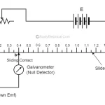 Null Type and Deflection Type Instruments