The permanent magnet moving coil instrument is the most accurate type of DC measurement.
It is one of the two types of moving coil instruments used to measure dc work only. The other moving coil instrument is a dynamometer type which can measure AC and DC work.
| Basic Range | 10 μA – 100 mA |
| Coil resistance | 10 Ω-1 kΩ |
| Usage | DC PMMC ammeters and voltmeters |
| Power Requirement | 25 μW – 200 μW |
| Accuracy | 2% – 5% |
Principle of PMMC Instruments
The action of the permanent magnet moving coil (PMMC) instrument is based on the motoring principle.
When a current-carrying coil is placed in the magnetic field produced by the permanent magnet, the coil experiences a force and moves.
As the coil is moving and the magnet is permanent, the instrument is called a permanent magnet moving coil instrument. This basic principle is called the D’Arsonval principle.
The amount of force experienced by the coil is proportional to the current passing through the Permanent coil.
The operation of a permanent-magnet moving-coil type instrument is be based upon the principle that when a current-carrying conductor is placed in a magnetic field, it is acted upon by a force that tends to move it to one side and out of the field.
Related: Moving Iron Instruments
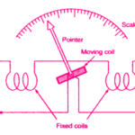
Construction of PMMC Instruments
The construction of a Permanent Magnet Moving Coil (PMMC) instrument is shown in the figure below.
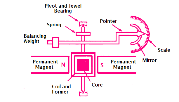
The moving coil is either rectangular or circular in shape. It has a number of turns of fine wire. The coil is suspended so that it is free to turn about its vertical axis.
The coil is placed in a uniform, horizontal and radial magnetic field of a permanent magnet in the shape of a horse-shoe.
The iron core is spherical if the coil is circular and is cylindrical if the coil is rectangular. Due to the iron core, the deflecting torque increases, increasing the sensitivity of the instrument.
The controlling torque is provided by two phosphor bronze hairsprings. The damping torque is provided by eddy current damping. It is obtained by movement of the aluminium former, moving in the magnetic field of the permanent magnet.
The pointer is carried by the spindle and it moves over a graduated scale. The pointer has lightweight so that it can deflect rapidly.
The mirror is placed below the pointer to get the accurate reading by removing the parallax. The weight of the instrument is normally counterbalanced by the weights situated diametrically opposite and rigidly connected to it.
The scale markings of the basic DC PMMC instruments are usually linearly spaced as the deflecting torque and hence the pointer deflection is directly proportional to the current passing through the coil.
In a practical PMMC instrument, a Y shaped member is attached to the fixed end of the front control spring. An eccentric pin through the instrument case engages the Y shaped member so that the zero position of the pointer can be adjusted from outside.
Working of PMMC Instruments
A Permanent Magnet Moving Coil (PMMC) instrument is shown in the figure.
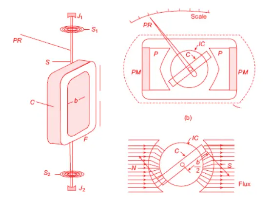
The coil C has a number of turns of thin insulated wires wound on a rectangular aluminium former F. The frame is carried on a spindle S mounted in jewel bearings J1, J2.
A pointer PR is attached to the spindle so that it moves over a calibrated scale. The whole of the moving system is made as light in weight as possible to keep the friction at the bearing to a minimum.
The coil is free to rotate in air gaps formed between the shaped soft-iron pole piece (pp) of a permanent magnet PM and a fixed soft-iron cylindrical core IC.
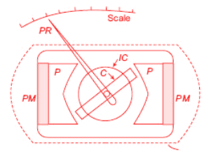
The core serves two purposes;
- it intensifies the magnetic field by reducing the length of the air gap
- it makes the field radial and uniform in the air gap.
Thus, the coil always moves at right angles to the magnetic field.
Modern permanent magnets are made of steel alloys which are difficult to machine. Soft-iron pole pieces (pp) are attached to the permanent magnet PM for easy machining in order to adjust the length of the air gap.
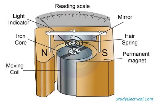
The figure below shows the internal parts of the Permanent Magnet Moving Coil (PMMC) instrument.
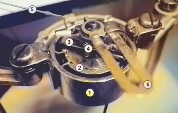
In the above figure, the components off PMMC instrument are shown as below,
- External Sheild
- Permanent magnet
- Moving Coil
- Control Spring
- Pointer
- Arrangement for zero balance of the pointer
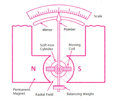
The next figure shows a schematic of the internal parts of a moving-coil instrument.
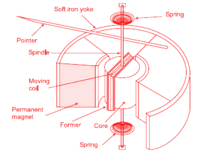
A soft-iron yoke (Y ) is used to complete the flux path and to provide shielding from stray external fields.
Watch the video animation to understand quickly the working of a moving coil instruments.
Torque Equation of PMMC Instrument
As you know, there are three types of torque acting on an instrument. In this section, you will derive and learn the equation of deflection torque, control torque and damping torque in a PMMC instrument.
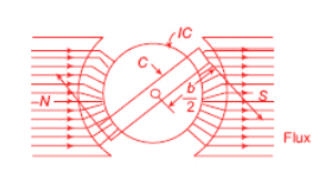
Let,
B = flux density in the air gap (wb/m2 )
i = current in the coil (A)
l = effective axial length of the coil (m)
b = breadth of the coil (m)
n = number of turns of the coil.
1. Deflection Torque in PMMC instrument
Force on one side of the coil is
F = Biln (N)
Torque on each side of the coil,
T = Force x distance from the axis of rotation
T = F × b/2
T = Biln × b/2
Total deflecting torque exerted on the coil,
Td = 2 × T = 2 × Biln x b/2
T = Bilnb (N-m)
For a permanent magnet, B is constant.
Also, for a given coil l, b and n are constants and thus the product (Blnb) is also a constant, say k1.
Therefore, Td = k1 × i
2. Control Torque
The control on the movement of the pointer over the scale is provided by two spirally wound, phosphor-bronze springs S1 and S2, one at each end of the spindle S. The deflection torque opposes the controlling torque.
Sometimes these springs also conduct the current into and out of the coil. The control torque of the springs is proportional to the angle θ turned through by the coil.
Tc = ks × θ
where Tc is the control torque and ks is the spring constant.
At final steady-state position, Control torque = Deflecting torque
Tc = Td
ks × θ = k1 × i
θ = k1 / ks × i = ki (where k = k1 / ks)
So, angular deflection of the pointer is directly proportional to the current. Thus the scale of the instrument is linear or uniformly divided.
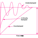
3. Damping Torque
When the aluminium former (F) moves with the coil in the field of the permanent magnet, a voltage is induced, causing eddy current to flow in it. These current exerts a force on the former.
By Lenz’s law, this force opposes the motion producing it. Thus, a damping torque is obtained. Such damping is called eddy-current damping.
Swamping Resistor
The coil of the instrument is made of copper. Its resistance varies with temperature.
A resistor of low-temperature coefficient is called the swamping resistor. A swamping resistor is connected in series with the coil. Its resistance practically remains constant with temperature. Hence the effect of temperature on coil resistance is swamped by this resistor.
Advantages of PMMC
The following are the advantages of a permanent magnet moving coil instrument.
- Sensitive to a small current
- Very accurate and reliable
- Uniform scale up to 270° or more
- Very effective built-in damping
- Low power consumption, varies from 25 µW to 200 µW
- Free from hysteresis and not affected by external fields because its permanent magnet shields the coil from external magnetic fields
- Easily adapted as a multirange instrument
Disadvantages of PMMC Instruments
Here are some of the disadvantages of PMMC instruments
- The biggest disadvantage is this type of instrument can be operated in direct current only. In alternating current, the instrument does not operate.
- It is because, in the positive half, the pointer experiences a force in one direction and in the negative half the pointer experiences the force in the opposite direction.
- Due to the inertia of the pointer, it retains it’s zero position.
- Their moving system is very delicate and can easily be damaged by rough handling.
- The coil being very fine, cannot withstand prolonged overloading.
- PMMC instruments are costlier.
- Aging of the instrument (permanent magnet and control spring) may introduce some errors.
Application of PMMC Instruments
Permanent-magnet moving-coil instruments can be used as ammeters (with the help of a low resistance shunt) or as voltmeters (with the help of a high series resistance).
The principle of permanent-magnet moving-coil type instruments has been utilized in the construction of the following :
- AC galvanometer
- Fluxmeter
- Ballistic Galvanometer
1. For AC galvanometer which can be used for detecting extremely small DC currents. A galvanometer may be used either as an ammeter (with the help of a low resistance) or as a voltmeter (with the help of a high series resistance).
2. By eliminating the control springs, the instrument can be used for measuring the quantity of electricity passing through the coil. This method is used for fluxmeter.
3. If the control springs of such an instrument are purposely made of a large moment of inertia, then it can be used as a ballistic galvanometer.
Extension Of Range Of PMMC Instruments
You can expend the range of a PMMC instrument used as an ammeter or voltmeter using the method explained in the next section.
Ammeter Shunts
When the PMMC instrument is used as an ammeter, its range can be extended with the help of a low-resistance shunt.
The moving-coil instrument has a coil wound with very fine wire. It can carry only a few mA safely to give full-scale deflection.
For measuring higher current, low resistance is connected in parallel to the instrument to bypass the major part of the current. The low resistance connected in parallel with the coil is called a shunt.
The figure below shows a shunt resistance Rsh connected in parallel with the basic meter.
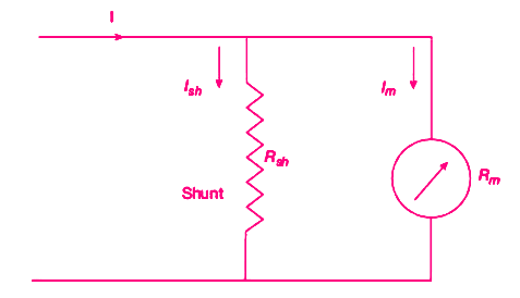
The resistance of the shunt can be calculated using conventional circuit analysis.
Rsh = shunt resistance (Ω)
Rm = coil resistance (Ω)
Im = Ifs = full-scale deflection current (A)
Ish = shunt current (A)
I = current to be measured (A)
The voltage drop across the shunt and the meter must be the same as they are connected in parallel.
Ish Rsh = Im Rm
I = Ish + Im
Ish = I – Im
From first equation,
Rsh = (Im / Ish ) Rm
Rsh = (Im / I – Im ) Rm
The ratio of the total current to the current in the meter is called the multiplying power of shunt. Multiplying power,
m = I/Im = 1 + Rm/Rsh
Rsh = Rm /(m-1)
Voltmeter Multipliers
The range of PMMC instrument, when used as a voltmeter, can be increased by using a high resistance in series with it.
For measuring higher voltages, a high resistance is connected in series with the instrument to limit the current in the coil to a safe value. This value of current should never exceed the current required to produce full-scale deflection.
The high resistance connected in series with the instrument is called a multiplier. In the figure, Rsc is the multiplier.
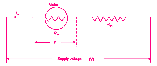
The value of multiplier required to extend the voltage range is calculated as under:
Rsc = multiplier resistance (Ω)
Rm = meter resistance (Ω)
Im = Ifs = full scale deflection current (A)
v = voltage across the meter for producing current Im (V)
V = voltage to be measured (V)
v = Im Rm
V = Im (Rm + Rsc)
Therefore,
Rsc = (V – Im Rm)/Im = V/Im – Rm
Now multiplying factor for multiplier,
m = V/v = Im (Rm + Rsc) / Im Rm = 1 + Rsc/Rm
Therefore, Rsc = (m-1)Rm
The sensitivity of PMMC Instrument
The moving-coil instrument is a very sensitive instrument. It is, therefore, widely used for measuring current and voltage.
The coil of the instrument may require a small amount of current (in the range of µA) for full-scale deflection. The sensitivity is sometimes expressed in ohm/volt. The sensitivity of a voltmeter is given by
S = (Total voltmeter resistance in Ohm) / (Full-scale reading in volts)
S = Rm/v
S = 1/Ifs (Ω/v)
where Ifs is the full-scale deflecting current.
Thus, the sensitivity depends upon the current to give full-scale deflection.
Errors in PMMC instrument
The basic sources of errors in PMMC instruments are friction, temperature, and aging of various parts. To reduce the frictional errors, the ratio of torque to weight is made very high.
The most serious errors are produced by the heat generated or by changes in the temperature. This changes the resistance of the working coil, causing large errors. In the case of voltmeters, a large series resistance of a very low-temperature coefficient is used. This reduces the temperature errors.
The aging of permanent magnet and control springs also cause errors. The weakening of magnet and springs cause opposite errors. The weakening of magnet cause less deflection while weakening of the control springs cause large deflection, for a particular value of current. The proper use of material and preageing during manufacturing can reduce the errors due to weakening of the control springs.
Related posts:
 Moving Iron Instruments – Attraction and Repulsion Type
 Electrodynamometer Instruments – Ammeter, Voltmeter and Wattmeter
 Damping Systems – Air friction, Fluid Friction & Eddy Current Damping
 Sinusoids and Phasors: Complete Guide
 6 Benefits of Buying an Industrial Video Borescope You Didn’t Know
 What are the Benefits and Advantages of Densitometer?
 The 5 Rules for Instrument Calibration
 Null Type and Deflection Type Instruments
 Accuracy and Precision in Measurements : Key Differences
 Moving Iron Instruments: Advantages and Disadvantages Explained