
Skip to content
StudyElectrical.Com
Search
  • Home
  • Basic Electrical
    • Magnetism
    • DC Circuits
  • Machines
    • Transformer
    • DC Generator
    • DC Motor
    • Three Phase Induction Motor
    • Alternator
    • Single Phase Motors
    • Synchronous Motor
  • Power System
    • Circuit Breaker
    • Electrical Relays
    • Substation
    • Transmission Line
    • Cables
    • Protection
  • Electronics
    • Power Electronics
    • Resistor
    • Microcontroller
    • Capacitor
    • PCB
    • Embedded System
  • Others
    • Measurement
    • Control System
    • Power Electronics
    • Signals and Systems
  • Blog
  • Search

Electrical Machines

Electrical Machines

Comprehensive technical notes on electrical power generation, T&D line parameters, switchgear, circuit breakers, protective relays, underground cables, and system stability.

Jump to:
Transformer
DC Generators
DC Motors
3-Phase Induction Motors
1-Phase Motors
Synchronous Motor
Alternator

Percentage Impedance of Transformer and Its Calculation
21/07/202626/05/2018 by Tesla
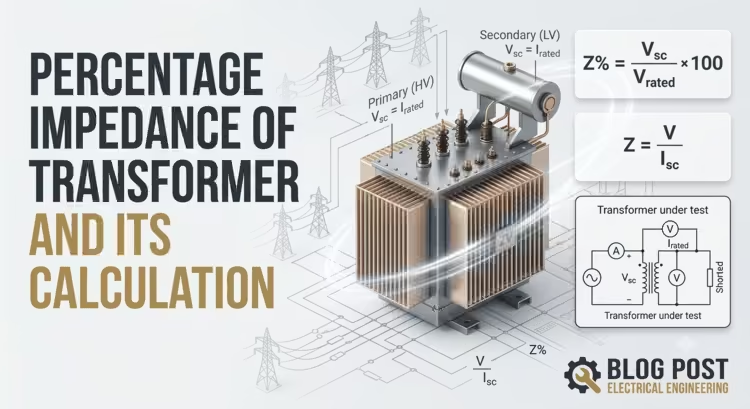
A detailed technical infographic illustrating percentage impedance in a transformer. The left side features a bold title: "PERCENTAGE IMPEDANCE OF TRANSFORMER AND ITS CALCULATION." The right side shows a 3D isometric illustration of a power transformer with cooling fins, bushings, and internal windings, labeled "Primary (HV)" and "Secondary (LV)." Above the transformer, two calculation boxes display the formulas Z% = (Vsc / Vrated) * 100 and Z = V / Isc. Below the transformer is a detailed circuit schematic for a "Transformer under test" showing a voltage source, ammeter, voltmeters, and shorted output. The background consists of a teal blueprint schematic, power line towers, and various electrical symbols. The StudyElectrical.com logo is in the bottom right corner.

The percentage impedance ($\%Z$) of a transformer is one of the most vital figures stamped on the nameplate of every … Read morePercentage Impedance of Transformer and Its Calculation
Categories Transformer, Electrical Machines, Uncategorized 5 Comments

Why Transformers are Rated in kVA, Not in kW? (With Proof)

16/07/202622/08/2014 by
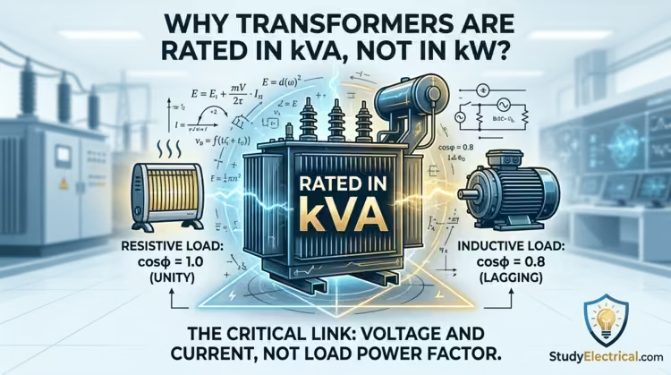
Featured image for StudyElectrical.com article explaining why transformers are rated in kVA not kW. The technical illustration shows a dynamic central transformer labeled 'RATED IN kVA' glowing with electric blue and gold energy, flanked by icons representing a resistive heater load (cosφ = 1.0) and an inductive motor load (cosφ = 0.8). Swirling equations and circuit diagrams surround the unit. The StudyElectrical logo is in the bottom corner.

Discover exactly why transformers are rated in kVA rather than kW. Learn how core and copper losses dictate a transformer’s thermal limit, explore the mathematical proof behind changing load power factors, and master this classic electrical engineering interview question.

Categories Transformer, Electrical Machines
Post navigation
Newer posts
← Previous 1 … 4 5

Study Electrical

Simplified electrical engineering notes, circuit breakdowns, and field reference guides for students, technicians, and power engineers.

  • Facebook
  • Threads
  • Instagram
  • X
  • YouTube
  • Pinterest

Category

  • Power System
  • Electrical Machines
  • Electronics
  • Measurement
  • Control System

Quick Links

  • About Us
  • Contact Us
  • Privacy Policy
  • Sitemap

Follow Us

Join our community on Instagram for daily infographics, schematics, and field notes.

Follow @studyelectrical →
© 2026 StudyElectrical. All rights reserved. | Built for Students & Engineers | Privacy Policy
© 2026 StudyElectrical.Com • Powered by GeneratePress