Three-phase transformers are used in three-phase circuits to step up and step down the voltage according to the needs in a power system.
You know that electric power is generated and transmitted using a three-phase system. The three-phase system has significant advantages over other polyphase systems. In a three-phase circuit, the voltage is raised or lowered by means of three-phase transformers.
Three-phase transformers functions just like three single-phase transformers. But a single three-phase transformer occupies less volume and weighs less than three single-phase transformers designed for the same purpose.
It is an electromagnetic energy converting device that has no moving parts and two (or more) windings fixed relative to each other, intended to transfer electric energy between circuits or systems by virtue of electromagnetic induction.
Two Ways of Three Phase Transformer Connection
A three-phase transformer in an electrical substation can be built in two ways
- By suitably connecting a bank of three single-phase transformers
- By constructing a three-phase transformer on a common magnetic structure.
In either case, the windings may be connected in four different connection methods.
- Star – Star Connection (Y-Y)
- Star – Delta Connection (Y-Δ)
- Delta – Delta Connection (Δ-Δ)
- Delta – Star Connection (Δ-Y)
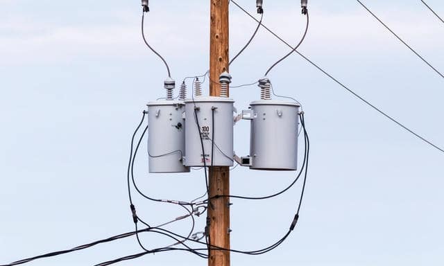
1. Bank of three single-phase transformers
Three similar single-phase transformers can be connected to form a three-phase transformer. The primary and secondary windings may be connected in star (Y) or delta (D) arrangement.
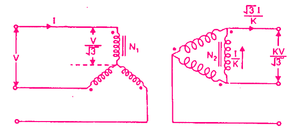
For example, the figure below shows a Y-D connection of a three-phase transformer. The primary windings are connected in star and the secondary windings are connected in delta.
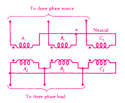
A more convenient way of showing this connection is illustrated below.
The primary and secondary windings shown parallel to each other belong to the same single-phase transformer. The ratio of secondary phase voltage to primary phase voltage is the phase transformation ratio K.
Phase transformation ratio, K = Secondary phase voltage / Primary phase voltage
Referring to the above figure, the primary line-to-line voltage is V and the primary line current is I.
The phase transformation ratio is K = ( N2 /N1 )
The secondary line voltage and line current are also shown.
As mentioned above, either Y or ∆ connections are possible with single-phase transformers connected in banks. It is extremely important that the single-phase transformers are carefully matched when they are banked together, especially when the ∆ connection is used. Using mismatched transformers in the ∆ connection will result in excessive circulating currents that will severely de-rate the bank or cause overheating.
Advantages
It may be impossible or impractical to fabricate or ship a three-phase transformer with an extremely large MVA capacity. A bank of three single-phase transformers may then be the solution, although the total size, weight, and cost of three single-phase units will probably exceed the size, weight, and cost of one three-phase unit.
An additional advantage of the bank arrangement is that a failure of one single-phase unit will usually be less costly to repair than a failure of a larger three-phase unit
One interesting configuration for a three-phase bank is the open delta connection used extensively in rural distribution systems. The open delta connection uses two single-phase transformers. An open Y-∆ connection requires only two phases plus the neutral on the primary side of the bank in order to develop a three-phase voltage at the secondary. This is an obvious cost-saving (in addition to the avoided cost of a third transformer) when the installation is far away from a three-phase primary circuit.
2. Single Unit Three-phase transformer
In the preceding section, we saw some of the ways that single-phase transformers can be connected in three-phase and two-phase systems. It is sometimes advantageous to construct a single three-phase transformer instead of using a bank of single-phase transformers.
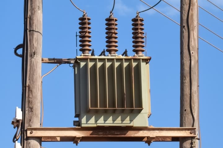
For instance, a three-phase transformer can often be more economical to build by enclosing one core and coil structure inside one transformer tank instead of building three separate core and coil structures and tanks.
A three-phase transformer can be constructed by having three primary and three secondary windings on a common magnetic circuit.
Principle of 3 Phase Transformer
The basic principle of a 3 phase transformer is explained below.
The three single-phase core-type transformers, each with windings (primary and secondary) on only one leg have their unwound legs combined to provide a path for the returning flux. The primaries, as well as secondaries, may be connected in star or delta.
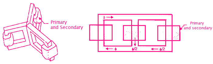
If the primary is energized from a 3-phase supply, the central limb (i.e., unwound limb) carries the fluxes produced by the 3-phase primary windings. Since the phasor sum of three primary currents at any instant is zero, the sum of three fluxes passing through the central limb must be zero. Hence no flux exists in the central limb and it may, therefore, be eliminated.
This modification gives a three-leg core-type 3-phase transformer. In this case, any two legs will act as a return path for the flux in the third leg.
For example, if the flux ϕ in one leg at some instant, then flux is ϕ/2 in the opposite direction through the other two legs at the same instant.
All the connections of a 3-phase transformer are made inside the case and for delta-connected winding three leads are brought out while for star connected winding four leads are brought out.
A common magnetic core three-phase transformer can also be either a core type or a shell type. Since the third harmonic flux created by each winding is in phase, a shell-type transformer is preferred because it provides an external path for this flux. In other words, the voltage waveforms are less distorted for a shell-type transformer than
for a core-type transformer of similar ratings
Advantages and Disadvantages of Single Unit 3 Phase Transformer
For the same capacity, a 3-phase transformer weighs less, occupies less space and costs about 20% less than a bank of three single-phase transformers. Because of these advantages, 3-phase transformers are in common use, especially for large power transformations.
A disadvantage of the single unit three-phase transformer lies in the fact that when one phase becomes defective, the entire three-phase unit must be removed from service. When one transformer in a bank of three single-phase transformers becomes defective, it may be removed from service and the other two transformers may be reconnected to supply service on an emergency basis until repairs can be made.
Three-Phase Transformer Connections
A three-phase transformer can be built by suitably connecting a bank of three single-phase transformers or by one three-phase transformer. The primary or secondary windings may be connected in either star (Y) or delta (D) arrangement.
The four most common connections are
- Star – Star Connection (Y-Y)
- Star – Delta Connection (Y-Δ)
- Delta – Delta Connection (Δ-Δ)
- Delta – Star Connection (Δ-Y)
These four connections are shown in the figure below. In this figure, the windings at the left are the primaries and those at the right are the secondaries. The primary and secondary voltages and currents are also shown. The primary line voltage is V and the primary line current is I. The phase transformation ratio K is given by;
K = Secondary phase voltage / Primary phase voltage = N2 /N1
Some of the advantages and drawbacks of each connection are highlighted below.
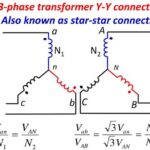
Star-Star (Y-Y) Connection
In the star-star (Y-Y) connection, 57.7% (or 3 / 1 ) of the line voltage is impressed upon each winding but full line current flows in each winding.
Power circuits supplied from a Y-Y bank often create serious disturbances in communication circuits in their immediate vicinity. Because of this and other disadvantages, the Y-Y connection is seldom used.
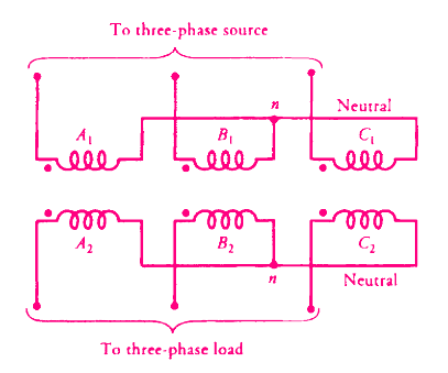
A Y/Y connection for the primary and secondary windings of a three-phase transformer is depicted in Figure. The line-to-line voltage on each side of the three-phase transformer is √3 times the nominal voltage of the single-phase transformer.
The main advantage of a Y/Y connection is that we have access to the neutral terminal on each side and it can be grounded if desired. Without grounding the neutral terminals, the Y/Y operation is satisfactory only when the three-phase load is balanced.
The electrical insulation is stressed only to about 57.7% of the line voltage in a Y-connected transformer.
Since most of the transformers are designed to operate at or above the knee of the curve, such a design causes the induced EMFs and currents to be distorted.
The reason is as follows: Although the excitation currents are still 120 degree out of phase with respect to each other, their waveforms are no more sinusoidal. These currents, therefore, do not add up to zero. If the neutral is not grounded, these currents are forced to add up to zero. Thus, they affect the waveforms of the induced EMFs.
Delta-Delta (Δ-Δ) Connection
The delta-delta (Δ-Δ) connection is often used for moderate voltages.
The line-to-line voltage on either side is equal to the corresponding phase voltage. Therefore, this arrangement is useful when the voltages are not very high.
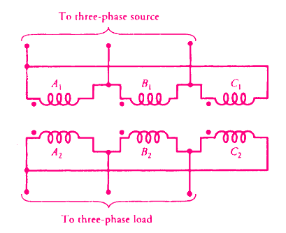
The advantage of this connection is that even under unbalanced loads the three-phase load voltages remain substantially equal.
The disadvantage of the Δ-Δ connection is the absence of a neutral terminal on either side. Another drawback is that the electrical insulation is stressed to the line voltage. Therefore, a Δ-connected winding requires more expensive insulation than a Y-connected winding for the same power rating.
A Δ-Δ connection can be analyzed theoretically by transforming it into a simulated Y/ Y connection using Δ-to-Y transformations.
Another advantage of this connection is that if one transformer gets damaged or is removed from service, the remaining two can be operated in what is known as the open-delta or V-V connection.
By being operated in this way, the bank still delivers three-phase currents and voltages in their correct phase relationships but the capacity of the bank is reduced to 57.7% of what it was with all three transformers in service.
Star-Delta (Y-Δ) Connection
This star-delta (Y-Δ) connection is very suitable for step-down applications. The secondary winding current is 57.7% of the load current.
On the primary side, the voltages are from line to neutral, whereas the voltages are from line to line on the secondary side. Therefore, the voltage and the current in the primary are out of phase with the voltage and the current in the secondary.
In a star-delta (Y-Δ) connection, the distortion in the waveform of the induced voltages is not as drastic as it is in a Y/ Y-connected transformer when the neutral is not connected to the ground. The reason is that the distorted currents in the primary give rise to a circulating current in the Δ-connected secondary. The circulating current acts more like a magnetizing current and tends to correct the distortion.
Delta-Star (Δ-Y) Connection
The Delta-Star (Δ-Y)connection is commonly used for stepping up to a high voltage. However, this connection is now being exploited to satisfy the requirements of both the three-phase and the single-phase loads.
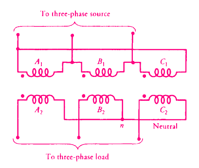
In this case, we use a four-wire secondary. The single-phase loads are taken care of by the three line-to-neutral circuits. An attempt is invariably made to distribute the single-phase loads almost equally among the three phases.
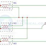

What is the current flow in primary winding if the secondary 1 & 2 windings draw 200A each for Dd0yn11 dry type transformer for 12-Pulse VFD system?