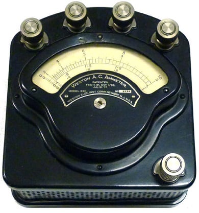
The most common ammeters and voltmeters for laboratory or switch-board use at power frequencies are the moving iron instruments.
These instruments can be constructed to measure current and voltage to the accuracy needed in most engineering works and still be cheap as compared with any other type of AC instrument of the same accuracy and ruggedness.
| Basic Range | 10 mA – 100 A |
| Usage | DC and AC moving iron ammeters and voltmeters |
There are two basic types of Moving Iron Instruments (MI instruments)
- Attraction-type moving-iron instruments
- Repulsion-type moving-iron instruments
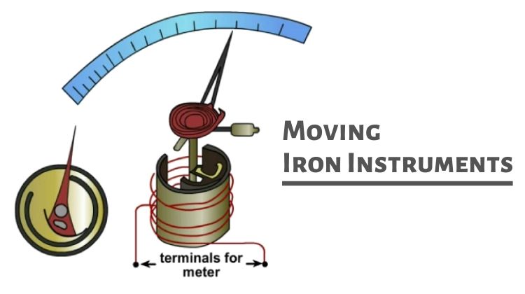
Working of Moving Iron Instruments
A plate or vane of soft iron or of high permeability steel forms the moving element of the system. This iron vane is so situated that it can move in a magnetic field produced by a stationary coil.
The coil is excited by the current or voltage under measurement.
When the coil is excited, it becomes an electromagnet and the iron vane moves in such a way so as to increase the flux of the electromagnet. This is because the vane tries to occupy a position of minimum reluctance.
Thus the force (or torque) produced is always in such a direction as to increase the inductance of the coil (As inductance increases as reluctance decreases).
The current to be measured, in general, is passed through a coil of wire in the moving iron instruments. In the case of voltage measurement, the current which is proportional to the voltage is measured.
The number of turns of the coil depends upon the current to be passed through it. For the operation of the instrument, a certain number of ampere-turns is required.
These ampere-turns can be produced by the product of a few turns and large current or reverse.
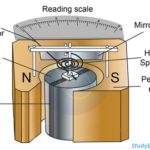
Attraction Type Moving Iron Instruments
The attraction type of moving iron instrument depends on the attraction of an iron vane into a coil carrying the current to be measured.
The figure shows an attraction-type moving iron (MI) instrument.
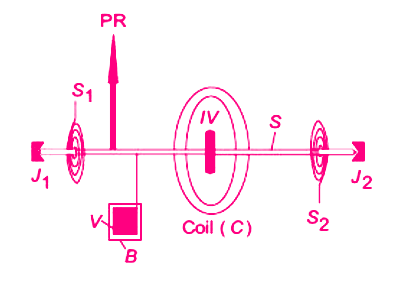
A soft iron vane IV is attached to the moving system. When the current to be measured is passed through the coil C, a magnetic field is produced. This field attracts the eccentrically mounted vane on the spindle towards it. The spindle is supported at the two ends on a pair of jewel bearings. Thus, the pointer PR, which is attached to the spindle S of the moving system is deflected. The pointer moves over a calibrated scale.
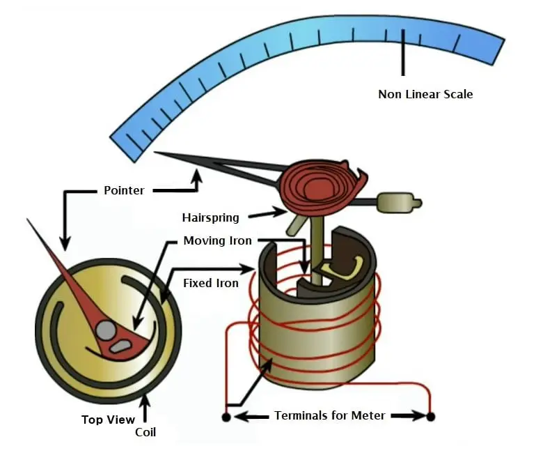
The control torque is provided by two hairsprings S1 and S2 in the same way as for a PMMC instrument, but in such instruments, springs are not used to carry any current.
Gravity control can also be used for vertically mounted panel type MI meters. The damping torque is provided by the movement of a thin vane V in a closed sector-shaped box B, or simply by a vane attached to the moving system.
Eddy current damping cannot be used in MI instruments owing to the fact that any permanent magnet that will be required to produce Eddy current damping can distort the otherwise weak operating magnetic field produced by the coil.
If the current in the fixed coil is reversed, the field produced by it also reverses. So the polarity induced on the vane reverses. Thus whatever be the direction of the current in the coil the vane is always be magnetized in such a way that it is attracted to the coil. Hence such an instrument can be used for both direct currents as well as alternating current.
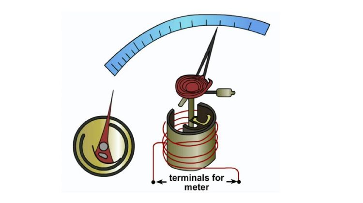
A sectional view of the actual instrument is shown in the figure. When the current to be measured is passed through the coil or solenoid, a magnetic field is produced, which attracts the eccentrically mounted disc inwards, thereby deflecting the pointer, which moves over a calibrated scale.
Repulsion-type Moving-Iron Instruments
In the repulsion type, there are two vanes inside the coil. One is fixed and the other is movable. These are similarly magnetized when the current flows through the coil and there is a force of repulsion between the two vanes resulting in the movement of the moving vane.
Two different designs for moving iron instruments commonly used are as follows:
- Radial Vane Type
- Co-axial Vane Type
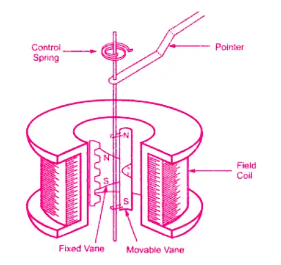
Radial Vane Type
In this type, the vanes are radial strips of iron. The strips are placed within the coil as shown in the figure.
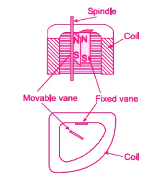
The fixed vane is attached to the coil and the movable one to the spindle of the instrument. The instrument pointer is attached to the moving vane spindle.
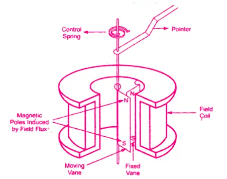
As current flows through the coil, the generated magnetic field induces identical polarities on both the fixed and moving vane. Thus, even when the current through the coil is alternating (for AC measurement), there is always a repulsion force acting between the like poles of fixed and moving vane. Hence deflection of the pointer is always in the same direction irrespective of the polarity of the current in the coil.
The amount of deflection depends on the repulsion force between the vanes which in turn depends on the amount of current passing through the coil. The scale can thus be calibrated to read the current or voltage directly.
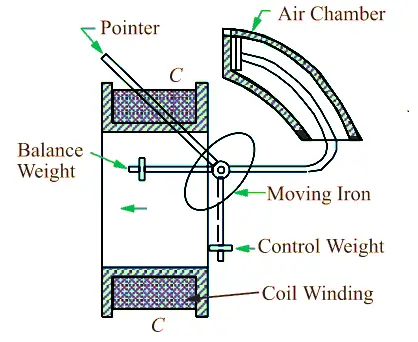
Co-axial Vane Type
In these types of instruments, the fixed and moving vanes are sections of coaxial cylinders as shown in the figure.
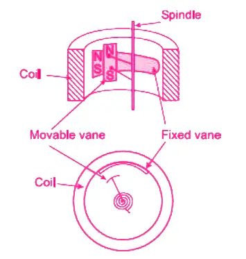
Current in the coil magnetizes both the vanes with similar polarity. Thus the movable vane rotates along the spindle axis due to this repulsive force. Coaxial vane type instruments are moderately sensitive as compared to radial vane type instruments that are more sensitive.
Moving iron instruments have their deflection is proportional to the square of the current flowing through the coil. These instruments are thus said to follow a square-law response and have non-uniform scale marking.
Deflection being proportional to the square of the current, whatever be the polarity of the current in the coil, deflection of a moving iron instrument is in the same direction. Hence, moving iron instruments can be used for both DC and AC measurements.
The video below shows the components inside a repulsion type moving iron ammeter.
Torque Equation of Moving-Iron Instruments
To deduce the expression for the torque of a moving iron instrument, energy relation can be considered for a small increment in current supplied to the instrument. This results in a small deflection dθ and some mechanical work will be done. Let Td be the deflecting torque.
∴ Mechanical work done = Torque × Angular displacement
= Td . dθ
Due to the change in inductance, there will be a change in the energy stored in the magnetic field.
Let I be the initial current, L be the instrument inductance and θ is the deflection. If the current increases by dl then it causes the change in deflection dθ and the inductance by dL.
In order to involve the increment dI in the current, the applied voltage must be increased by:
e = dϕ/dt = d/dt (LI) = I (dL/dt) + L (dI/dt)
The electrical energy supplied is eldt = I2dL + ILdl
Substitute the value of edt from above equation
The current is changes from I to (I + dI), and the inductor L to (L + dL).
Therefore the stored energy changes from ½I2L to ½(I + dI)2(L + dL)
Hence the change in energy storage = ½(I + dI)2(L + dL) – ½I2L
As dI and dL are very small, neglecting the second and higher order terms in small quantities, this becomes
IL.dL + ½I2dL
From the principle of conservation of energy,
Electrical energy supplied = Increase in stored energy + Mechanical work done.
I2dL + ILdl = IL.dL + ½ I2dL + Td . dθ
∴ Td . dθ = ½I2dL
Deflecting torque, Td = ½ I2(dL/dθ)
where Td is in newton-meter, I is in ampere, L is in henry and θ is in radians.
The moving system is provided with control springs and in turn, the deflecting torque Td is balanced by the controlling torque
Tc = k θ
where k is the control spring constant (N-m/rad) and θ is the deflection in radians.
At the final steady position, Tc = Td
k θ = ½ I2 (dL/dθ)
∴ Deflection, θ = ½ (I2/k)( dL/dθ)
Hence, the deflection is proportional to the square of the RMS value of the operating current. The deflection torque is, therefore, unidirectional whatever may be the polarity of the current.
Advantages of Moving Iron Instruments
The important advantages of moving iron instruments are
- Robust construction and relatively cheap
- Suitable for measuring both dc and ac
- Can withstand overload momentarily
Disadvantages of Moving Iron Instruments
The following are the disadvantages of moving iron instruments
- As the deflection is proportional to I2, hence the scale of the instrument is not uniform. It is cramped in the lower end and expanded in the upper portion.
- It is affected by stray magnetic fields.
- There is a hysteresis error in the instrument. The hysteresis error may be minimized by using the vanes of nickel-iron alloy. Read Errors in Moving Iron Instruments
- When used for measuring ac the reading may be affected by the variation of frequency due to the change in reactance of the coil, which has some inductance. With the increase in frequency, iron loses and coil impedance increases.
- Since a large amount of power is consumed to supply I2R loss in the coil and magnetic losses in the vanes, it is not a very sensitive instrument.


Nice article. I didn’t get such a complete explanation about moving iron instruments anywhere in internet. You explained everything in this article. Thank you