Inductors are electrical components that oppose the flow of alternating current (AC) by temporarily storing energy as magnetic fields. The action of an inductor is known as Inductance.
This article discusses inductors and inductance. By the end of this article, you will learn the following.
- What is inductor and inductance and how they work?
- What are the different types of inductors?
- Series and parallel inductors and their connection
- Mutual inductance and coefficient of coupling.
- Advantages and disadvantages of different types of inductors
Inductors often, but not always, consist of wire coils. Sometimes a length of wire, or a pair of wires, is used as an inductor.
What is Inductance?
Suppose you have a wire 1 million miles long (about 1.6 million kilometers). Imagine that you make this wire into a huge loop, and connect its ends to the terminals of a battery as shown in the figure below. An electrical current will flow through the loop of wire, but this is only part of the picture.
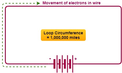
If the wire was short, the current would begin to flow immediately, and it would attain a level limited by the resistance in the wire and in the battery.
But because the wire is extremely long, it takes a while for the electrons from the negative terminal to work their way around the loop to the positive terminal. It will take a little time for the current to build up to its maximum level.
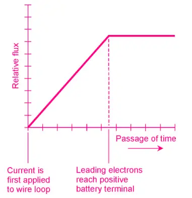
The magnetic field produced by the loop will be small during the first few moments when current flows in only part of the loop. The magnetic field will build up as the electrons get around the loop. Once a steady current is flowing around the entire loop, the magnetic field will have reached its maximum quantity and will level off.
A certain amount of energy is stored in this magnetic field. The amount of stored energy depends on the inductance of the loop, which is a function of its overall size.
Inductance, as a property or as a mathematical variable, is symbolized by an italicized, uppercase letter L.
The loop constitutes an inductor, the symbol for which is an uppercase, nonitalicized letter L.
Practical Inductors
It is impractical to make wire loops 1 million miles in circumference. But lengths of wire can be coiled up. When this is done, the magnetic flux is increased for a given length of wire compared with the flux produced by a single-turn loop.
The magnetic flux density inside a coil is multiplied when a ferromagnetic core is placed within it.
The increase in flux density has the effect of increasing the inductance, too. So, Inductance (L) is many times greater with a ferromagnetic core than with an air core or a nonmagnetic core such as plastic or wood.
The current that an inductor can handle depends on the diameter (gauge) of the wire. But the value of inductance L is a function of the number of turns in the coil, the diameter of the coil itself, and the overall shape of the coil.
In general, the inductance of a coil is directly proportional to the number of turns of wire.
Inductance is directly proportional to the diameter of the coil. The length of a coil, given a certain number of turns and a certain diameter, has an effect as well.
If a coil having a certain number of turns and a certain diameter is “stretched out,” its inductance decreases. Conversely, if it is “squashed up,” its inductance increases.
The Unit of Inductance
When a battery is first connected across an inductor, the current builds up at a rate that depends on the inductance. The greater the inductance, the slower the rate of current buildup for a given battery voltage.
The unit of inductance is an expression of the ratio between the rate of current buildup and the voltage across an inductor. An inductance of 1 henry (1 H) represents a potential difference of 1 volt (1 V) across an inductor within which the current is changing at the rate of 1 ampere per second (1 A/s).
Henry is a huge unit of inductance. You won’t often see an inductor this large, although some power-supply filter chokes have inductances up to several henrys.
Usually, inductances are expressed in millihenrys (mH), microhenrys (µH), or nanohenrys (nH). You should know your prefix multipliers by now, but in case you’ve forgotten:
1 mH = 0.001 H = 10-3 H
1 µH = 0.001 mH = 10-6 H
1 nH = 0.001 µH = 10-9 H
Small coils with few turns of wire produce small inductances, in which the current changes quickly and the induced voltages are small.
Large coils with ferromagnetic cores, and having many turns of wire, have high inductances in which the current changes slowly and the induced voltages are large.
The current from a battery, building up or dying down through a high-L coil, can give rise to a deadly potential difference between the end terminals of the coil—many times the voltage of the battery itself. This is how spark coils work in internal combustion engines. Be careful around them!
Inductors in Series
When the magnetic fields around inductors do not interact, inductances in series add like resistances in series. The total value is the sum of the individual values.
It’s important to be sure that you are using the same size units for all the inductors when you add their values. After that, you can convert the result to any inductance unit you want.
Example 1
Suppose three 40.0-µH inductors are connected in series, and there is no interaction, or mutual inductance, among them. What is the total inductance?
Add up the values.
Call the inductances of the individual components L1 , L2 , and L3 , and the total inductance L.
Then L = L1 + L2 + L3 = 40.0 + 40.0 + 40.0 = 120 µH.
Example 2
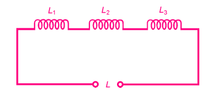
Imagine three inductors, with no mutual inductance, with values of 20.0 mH, 55.0 µH, and 400 nH. What is the total inductance, in millihenrys, of these components if they are connected in series as shown in the figure?
First, convert all the inductances to the same units. Microhenrys are a good choice because that unit makes the calculation process the least messy.
Call L1 = 20.0 mH = 20,000 µH, L2 = 55.0 µH, and L3 = 400 nH = 0.400 µH.
The total inductance is therefore L = 20,000 + 55.0 + 0.400 = 20,055.4 µH.
This is 20.1 mH after converting and rounding off.
Inductors in Parallel
If there is no mutual inductance among two or more parallel-connected inductors, their values add up like the values of resistors in parallel.
Suppose you have inductances L1, L2, L3,. . . , Ln all connected in parallel.
Then you can find the reciprocal of the total inductance, 1/L, using the following formula:
1/L = 1/L1 + 1/L2 + 1/L3 + . . . + 1/Ln
The total inductance, L, is found by taking the reciprocal of the number you get for 1/L.
Again, as with inductances in series, it’s important to remember that all the units have to agree during the calculation process. Once you have completed the calculation, you can convert the result to any inductance unit.
Example 1
Suppose there are three inductors, each with a value of 40 µH, connected in parallel with no mutual inductance, as shown in the figure. What is the net inductance of the combination?
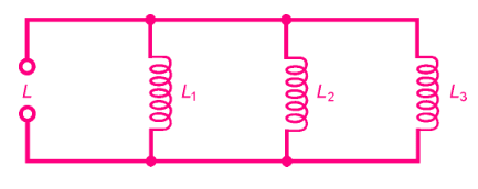
Let’s call the inductances L 1 = 40 µH, L 2 = 40 µH, and L 3 = 40 µH.
Use the preceding formula to obtain 1/L = 1/40 + 1/40 + 1/40 = 3/40 = 0.075. Then L = 1/0.075 = 13.333 µH.
This should be rounded off to 13 µH because the original inductances are specified to only two significant digits.
Example 2
Imagine four inductors in parallel, with no mutual inductance and values of L 1 = 75.0 mH, L 2 = 40.0 mH, L 3 = 333 µH, and L 4 = 7.00 H. What is the net inductance of this combination?
You can use henrys, millihenrys, or microhenrys as the standard units in this problem. Suppose you decide to use Henry.
Then L 1 = 0.0750 H, L 2 = 0.0400 H, L 3 = 0.000333 H, and L 4 = 7.00 H.
Use the preceding formula to obtain 1/L = 13.33 + 25.0 + 3003 + 0.143 = 3041.473.
The reciprocal of this is the inductance L = 0.00032879 H = 328.79 µH.
This should be rounded off to 329 µH. This is only a little less than the value of the 333 µH inductor alone.
If there are several inductors in parallel, and one of them has a value that is much smaller than the values of all the others, then the total inductance is a little smaller than the value of the smallest inductor.
Interaction among Inductors
In real-world circuits, there is almost always some mutual inductance between or among solenoidal coils. The magnetic fields extend significantly outside such coils, and mutual effects are difficult to avoid or eliminate.
The same is true between and among lengths of wire, especially at high ac frequencies. Sometimes, mutual inductance has no detrimental effect, but in some situations, it is not wanted.
Mutual inductance can be minimized by using shielded wires and toroidal inductors. The most common shielded wire is a coaxial cable.
Toroidal inductors are discussed later in this article.
Coefficient of Coupling
The coefficient of coupling, symbolized k, is an expression of the extent to which two inductors interact.
It is specified as a number ranging from 0 (no interaction) to 1 (the maximum possible interaction).
Two coils separated by a sheet of solid iron, or by a great distance, have a coefficient of coupling of zero (k = 0). Two coils wound on the same form, one right over the other, have the maximum possible coefficient of coupling (k = 1).
Sometimes, the coefficient of coupling is multiplied by 100 and expressed as a percentage from 0 to 100 percent.
Mutual Inductance
The mutual inductance between two inductors is symbolized M, and is expressed in the same units as inductance: henrys, millihenrys, microhenrys, or nanohenrys.
The value of M is a function of the values of the inductors, and also of the coefficient of coupling.
In the case of two inductors having values of L1 and L2 (both expressed in the same size units), and with a coefficient of coupling equal to k, the mutual inductance M is found by multiplying the inductance values, taking the square root of the result, and then multiplying by k.
Mathematically:
M = k √(L1 L2)
where the √ represents the square root.
The value of M thus obtained will be in the same size unit as the values of the inductance you input to the equation.
Effects of Mutual Inductance
Mutual inductance can either increase or decrease the net inductance of a pair of series-connected coils, compared with the condition of zero mutual inductance.
The magnetic fields around the coils either reinforce each other or oppose each other, depending on the phase relationship of the ac applied to them.
If the two ac waves (and thus the magnetic fields they produce) are in phase, the inductance is increased compared with the condition of zero mutual inductance. If the two waves are in the opposing phase, the net inductance is decreased relative to the condition of zero mutual inductance.
When two inductors are connected in series and there is reinforcing mutual inductance between them, the total inductance L is given by the following formula:
L = L1 + L2 + 2M
where L 1 and L 2 are the inductances, and M is the mutual inductance.
All inductances must be expressed in the same size units.
When two inductors are connected in series and the mutual inductance is opposing, the total inductance L is given by this formula:
L = L1 + L2 − 2M
where, again, L 1 and L 2 are the values of the individual inductors.
It is possible for mutual inductance to increase the total series inductance of a pair of coils by as much as a factor of 2, if the coupling is total and if the flux reinforces. Conversely, it is possible for the inductances of two coils to completely cancel each other.
If two equal-valued inductors are connected in series so their fluxes oppose (or buck each other) and k = 1, the result is theoretically zero inductance.
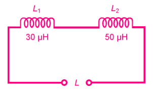
Example 1
Suppose two coils, having inductances of 30 µH and 50 µH, are connected in series so that their fields reinforce, as shown in the figure. Suppose that the coefficient of coupling is 0.500. What is the total inductance of the combination?
First, calculate M from k.
According to the formula for this, given previously, M = 0.500(50 × 30) 1/2 = 19.4 µH.
Then figure the total inductance.
It is equal to L = L 1 + L 2 + 2M = 30 + 50 + 38.8 = 118.8 µH, rounded to 120 µH because only two significant digits are justified.
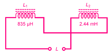
Example 2
Imagine two coils with inductances of L 1 = 835 µH and L 2 = 2.44 mH. Suppose they are connected in series so that their coefficient of coupling is 0.922, acting so that the coils oppose each other, as shown in the figure. What is the net inductance of the pair?
First, calculate M from k.
The coil inductances are specified in different units. Let’s use microhenrys for our calculations, so L 2 = 2440 µH.
Then M = 0.922(835 × 2440) 1/2 = 1316 µH.
Then figure the total inductance. It is L = L 1 + L 2 − 2M = 835 + 2440 − 2632 = 643 µH.
Types of Inductors
There are different types of inductors. Depending on the type of core material used, inductors are categorized into the following.
- Air Core Inductor
- Iron Core Inductor
- Ferrite Core Inductor
- Iron Powder Inductor
- Laminated Core inductor
- Toroidal Inductor
- Ceramic Inductor
- Film Layer Inductor
- Variable Inductor
- Coupled Inductors
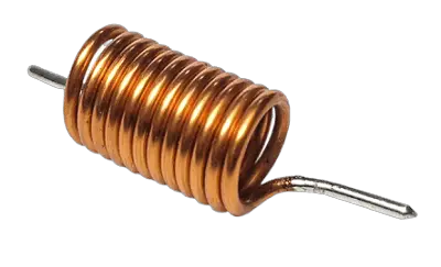
Air-Core Inductor
The simplest inductors (besides plain, straight lengths of wire) are coils.
A coil can be wound on a hollow cylinder of plastic or other nonferromagnetic material, forming an air-core coil. In practice, the maximum attainable inductance for such coils is about 1 mH.
Air-core coils are used mostly in radio-frequency transmitters, receivers, and antenna networks.
In general, the higher the frequency of ac, the less inductance is needed to produce significant effects. Air-core coils can be made to have the almost unlimited current-carrying capacity, simply by using heavy-gauge wire and making the radius of the coil large. Air does not dissipate much energy in the form of heat. It’s efficient, even though it has low permeability.
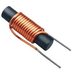
Ferromagnetic Cores
Ferromagnetic substances can be crushed into dust and then bound into various shapes, providing core materials that greatly increase the inductance of a coil having a given number of turns.
Depending on the mixture used, the increase in flux density can range from a factor of a few times, up through many thousands of times. A small coil can thus be made to have a large inductance.
There are two main types of ferromagnetic material in common use as coil cores. These substances are known as powdered iron and ferrite.
- Powdered Iron Cores
- Ferrite Core
Advantages and Limitations of Ferromagnetic Cores
Powdered-iron cores are common at high and very high radio frequencies.
A ferrite is a special form of powdered iron that has exceptionally high permeability, causing a great concentration of magnetic flux lines within the coil.
Ferrite is used at audio frequencies, as well as at low, medium, and high radio frequencies. Coils using these materials can be made much smaller, physically, than can air-core coils having the same inductance.
The main trouble with ferromagnetic cores is that, if the coil carries more than a certain amount of current, the core will saturate. This means that the ferromagnetic material is holding as much flux as it possibly can.
When a core becomes saturated, any further increase in coil current will not produce a corresponding increase in the magnetic flux in the core. The result is that the inductance changes, decreasing with coil currents that are more than the critical value.
In extreme cases, ferromagnetic cores can also waste considerable power as heat. This makes a coil lossy.
Permeability Tuning
Solenoidal coils can be made to have variable inductance by sliding ferromagnetic cores in and out of them. The frequency of a radio circuit can be adjusted in this way.
Because moving the core in and out of a coil changes the effective permeability within the coil, this method of tuning is called permeability tuning. The in/out motion can be precisely controlled by attaching the core to a screw shaft, and anchoring a nut at one end of the coil.
As the screw shaft is rotated clockwise, the core enters the coil, and the inductance increases. As the screw shaft is rotated counterclockwise, the core moves out of the coil, and the inductance decreases.
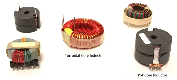
Toroids
Inductor coils do not have to be wound on cylindrical forms, or on cylindrical ferromagnetic cores. There’s another coil geometry, called the toroid.
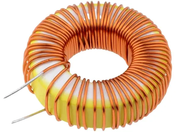
Toroid gets its name from the shape of the ferromagnetic core. The coil is wound over a core having this shape which resembles a donut or bagel.
There are several advantages to toroidal coils over solenoidal, or cylindrical, ones.
- First, fewer turns of wire are needed to get a certain inductance with a toroid compared to a solenoid.
- Second, a toroid can be physically smaller for a given inductance and current-carrying capacity.
- Third, practically all the flux is contained within the core material. This reduces unwanted mutual inductances with components near the toroid.
Toroidal coils have limitations, too.
- It is more difficult to permeability-tune a toroidal coil than it is to tune a solenoidal one.
- Toroidal coils are harder to wind than solenoidal ones.
- Sometimes, mutual inductance between or among physically separate coils is actually desired; with a toroid, the coils have to be wound on the same form for this to be possible.
Pot Cores
There is another way to confine the magnetic flux in a coil so that unwanted mutual inductance does not occur: wrap ferromagnetic core material around a coil. A wraparound core of this sort is known as a pot core.
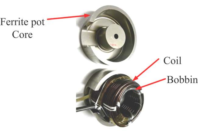
A typical pot core comes in two halves, inside one of which the coil is wound. Then the parts are assembled and held together by a bolt and nut. The entire assembly looks like a miniature oil tank. The wires come out of the core through small holes or slots.
Pot cores have the same advantages as toroids.
The core tends to prevent the magnetic flux from extending outside the physical assembly. Inductance is greatly increased compared to solenoidal windings having a comparable number of turns.
In fact, pot cores are even better than toroids if the main objective is to get a large inductance in a small space.
The main disadvantage of a pot core is that tuning, or adjustment of the inductance, is all but impossible. The only way to do it is by switching in different numbers of turns, using taps at various points on the coil.
Filter Chokes
The largest values of inductance that can be obtained in practice are on the order of several henrys.
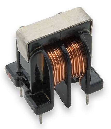
The primary use of a coil this large is to smooth out the pulsations in direct current that result when ac is rectified in a power supply. This type of coil is known as a filter choke.
Inductors at AF
Inductors for audio frequency (AF) applications range in value from a few millihenrys up to about 1 H. They are almost always toroidally wound, or are wound in a pot core, or comprise part of an audio transformer. Ferromagnetic cores are the rule.
Inductors can be used in conjunction with moderately large values of capacitance in order to obtain AF-tuned circuits. However, in recent years, audio tuning has been largely taken over by active components, particularly integrated circuits.
Inductors at RF
The radiofrequency (RF) spectrum ranges from a few kilohertz to well above 100 GHz. At the low end of this range, inductors are similar to those at AF. As the frequency increases, cores having lower permeability are used.
Toroids are common up through about 30 MHz. Above that frequency, air-core coils are more often used.
In RF applications, coils are routinely connected in series or in parallel with capacitors to obtain tuned circuits.
Other arrangements yield various characteristics of attenuation versus frequency, serving to let signals at some frequencies pass through while rejecting signals at other frequencies.
Transmission-Line Inductors
At frequencies about 100 MHz, another type of inductor becomes practical. This is the type formed by a length of the transmission line.
A transmission line is generally used to get energy from one place to another. In radio communications, transmission lines get energy from a transmitter to an antenna, and from an antenna to a receiver.
Most transmission lines are found in either of two geometries,
- parallel-wire transmission line
- coaxial type transmission line
A parallel-wire transmission line consists of two wires running alongside each other with constant spacing.
The spacing is maintained by polyethylene rods molded at regular intervals to the wires, or by a solid web of polyethylene. The substance separating the wires is called the dielectric of the transmission line.
A coaxial transmission line has a wire conductor surrounded by a tubular braid or pipe. The wire is kept at the center of this tubular shield by means of polyethylene beads, or more often, by solid or foamed polyethylene, all along the length of the line.
Line Inductance
Short lengths of any type of transmission line behave as inductors, as long as the line length is less than 90° ( 1⁄4 of a wavelength).
At 100 MHz, 90° in free space is 75 cm, or a little more than 2 ft. In general, if f is the frequency in megahertz, then 1⁄4 wavelength in free space, expressed in centimeters (s cm ), is given by this formula:
Scm = 7500/f
The length of a quarter-wavelength section of the transmission line is shortened from the free-space quarter wavelength by the effects of the dielectric.
In practice, 1 ⁄ 4 wavelength along the line can be anywhere from about 0.66 (or 66 percent) of the free-space length for coaxial lines with solid polyethylene dielectric to about 0.95 (or 95 percent) of the free-space length for parallel-wire line with spacers molded at intervals of several centimeters. The factor by which the wavelength is shortened is called the velocity factor of the line.
The shortening of the wavelength in a transmission line, compared with the wavelength in free space, is a result of a slowing down of the speed with which the radio signals move in the line compared with their speed in space (the speed of light).
If the velocity factor of a line is given by v, then the preceding formula for the length of a quarter-wave line, in centimeters, becomes:
Scm = 7500v/f
Very short lengths of line—a few electrical degrees—produce small values of inductance. As the length approaches 1⁄4 wavelength, the inductance increases.
Transmission line inductors behave differently than coils in one important way: the inductance of a coil, particularly an air-core coil, is independent of the frequency.
But the inductance of a transmission-line section changes as the frequency changes. At first, the inductance becomes larger as the frequency increases. At a certain limiting frequency, the inductance becomes theoretically infinite.
Above that frequency, the line becomes capacitive rather than inductive. Learn more about capacitors and capacitance.
Unwanted Inductances
Any length of wire has some inductance. As with a transmission line, the inductance of a wire increases as the frequency increases. Wire inductance is more significant at RF than at AF.
In some cases, especially in radio communications equipment, the inductance of, and among, wires can become a major problem. Circuits can oscillate when they should not. A receiver might respond to signals that it’s not designed to intercept.
A transmitter can send out signals on unauthorized and unintended frequencies. The frequency response of any circuit can be altered, degrading the performance of the equipment. Sometimes the effects of this stray inductance are so small that they are not important; this might be the case in a stereo hi-fi set located at a distance from other electronic equipment. But in some situations, stray inductance can cause serious equipment malfunctions.
A good way to minimize stray inductance is to use coaxial cables between and among sensitive circuits or components. The shield of the cable is connected to the common ground of the apparatus.
In some cases, enclosing individual circuits in metal boxes can prevent stray inductance from causing feedback and other problems.