In this article, you will learn different types of substation bus configuration and their application.
The equipment and buses installed in the substation switchyard are arranged and connected in specific ways to form bus configurations.
The industry has developed several standard bus configurations that vary in complexity, cost, and reliability.
The standard bus configurations/scheme are
- Radial bus
- Sectionalized radial bus
- Main and transfer bus
- Single breaker double bus
- Ring bus
- One-half breaker
- Breaker and one-half
- Double breaker double bus.
The layout of a substation for any particular configuration may vary to accommodate differences in equipment type, size and arrangement, and site-specific criteria.
1. Radial Bus Configuration
The radial bus configuration consists of one main bus. The transmission lines, transformers, and shunt capacitor banks are connected to the main bus through circuit breakers, circuit switchers, or motor operated or manually operated disconnect switches.
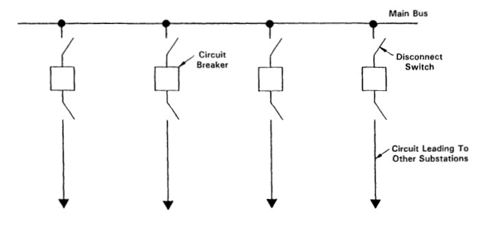
Radial bus substations are the simplest to operate. But they have the least system reliability and flexibility of operation.
- Bus faults and failure of a breaker to operate for a fault require an outage of the complete substation.
- In radial bus substations, it is necessary to take an outage of a circuit to perform periodic or emergency maintenance on its associated circuit breaker.
As shown in the figure, breaker bypass switches can be installed to allow removal of a circuit breaker from service for maintenance without an outage of the associated circuit, but this leaves the circuit without relay protection.
When the breaker is isolated for maintenance, the bypass switch is closed, and the circuit breaker and its associated disconnect switches are opened.
All protective relaying and control for the circuit at the local substation are removed from service when the circuit breaker is isolated.
A fault on the circuit with its associated circuit breaker bypassed requires an outage of the complete substation.
Advantages and Disadvantages of Radial Bus Configuration
Advantages of the radial bus substations over other configurations are the lowest cost, small required land area, ease of expansion, simple operation, and simple protective relaying.
Disadvantages of radial bus configuration substations include low reliability, low flexibility of operation for maintenance, and the removal of the substation from service in cases of bus faults and failure of a breaker.
Application
The radial bus configuration is generally applied in substations from distribution voltage through 161 kV and in locations where system reliability is not critical.
2. Sectionalized Radial Bus Configuration
The sectionalized or split radial bus is a modification of the radial bus. This configuration is two radial buses tied together through a sectionalizing or bus tie circuit breaker.
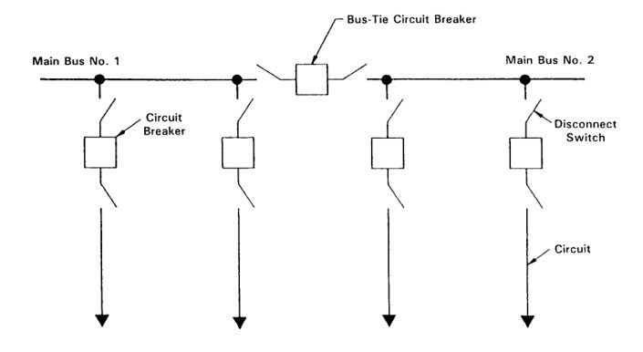
The sectionalizing circuit breaker can be operated normally open or normally closed, depending on system requirements.
Bus faults or the failure of a breaker (other than the tiebreaker) to operate for a fault requires an outage of only the affected bus section.
The grouping of circuits on bus sections is determined by examining system operating criteria.
- Circuits should be arranged to prevent outages on similar or redundant circuits.
- Circuits fed from the same source or circuits feeding the same load should be on different bus sections.
Breaker bypass switches can be applied in sectionalized radial bus substations and operate the same as in radial bus substations.
Advantages and Disadvantages of Sectionalized Radial Bus
Sectionalized radial bus substations offer the advantages of
- small land area,
- increased reliability over the radial bus,
- increased flexibility of operation over the radial bus,
- and ease of expansion.
Disadvantages, when compared to the radial bus include
- increased cost,
- increased complexity of operation,
- and increased complexity of protective relaying.
Application
The sectionalized radial bus configuration is generally applied in substations from distribution voltage through 161 kV and in locations where system reliability is not critical.
3. Main and Transfer Bus
The main and transfer bus is another modification of the radial bus. This configuration consists of a main bus and a transfer bus.
All circuits are connected to the main bus through circuit breakers and to the transfer bus through transfer switches. The main and transfer buses are connected through a transfer bus circuit breaker.
The transfer bus circuit breaker protects a circuit during maintenance of its associated circuit breaker.
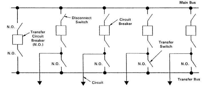
When a circuit breaker is removed from service for maintenance, the transfer circuit breaker and its associated disconnect switches are closed, the transfer switch for the circuit breaker to be serviced is closed, and the circuit breaker to be maintained and its associated disconnect switches are opened. Reliability and protection are not compromised during maintenance.
Considerable attention must be given to the selection of the protective relaying for the transfer circuit
breaker.
Advantages and Disadvantages
The advantages of main and transfer bus substations when compared to other configurations include the
- small land area required,
- ease of expansion,
- increased flexibility of operation over the radial bus or split radial bus,
- and the fact that any breaker can be removed from service without an outage of the circuit served.
Disadvantages over the radial bus are
- the increased cost,
- increased complexity of the operation,
- increased complexity of protection,
- and no improvement in reliability.
Application:
The main and transfer bus configuration is generally applied in substations from distribution voltage through 161 kV and in locations where system reliability is not critical.
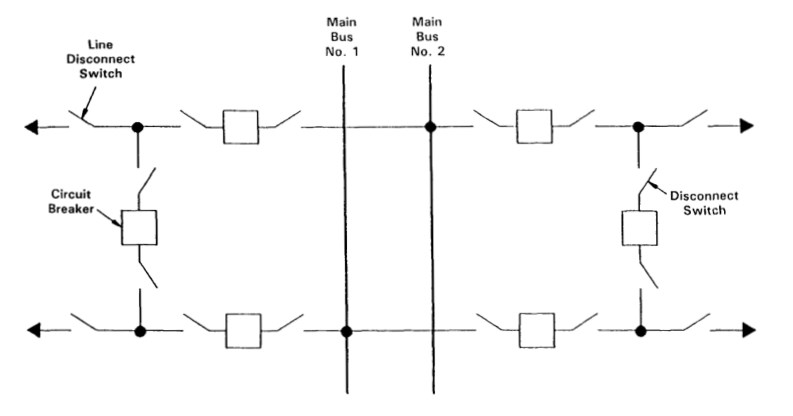
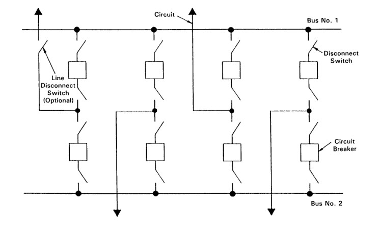
4. Single Breaker Double Bus Configuration
The single breaker double bus configuration is a modification of the sectionalized radial bus. This configuration consists of two main buses connected through a tie circuit breaker.
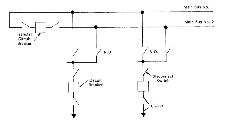
Each circuit has one circuit breaker that can be connected to either the main bus through disconnect switches.
This configuration allows circuits to be connected to either the main bus to balance the load, separate critical circuits, or place sources on each bus and allows all circuits to be connected to one bus in case of an outage on the other bus.
The switching of a circuit from one bus to the other is not automatic and requires manual switching.
Advantages, Disadvantages & Application
Single breaker, double bus substations have the same advantages and disadvantages as the split bus radial, and additional disadvantages including increased cost over the split radial bus increased complexity of protective relaying over the split radial bus because of the requirement for switching of bus relaying current transformer secondary circuits.
The single breaker double bus configuration is generally applied in substations from distribution voltage through 161 kV and in locations where system reliability is not critical.
It is also the least common of the radial bus configurations discussed.
5. Ring Bus Configuration
The ring bus configuration is, in reality, a series of sectionalized radial buses connected together to form a ring. Each bus is called a position.
Sometimes a transmission line and a transformer are paired on one ring position. In this configuration, only one position is removed from service for a circuit or bus fault.
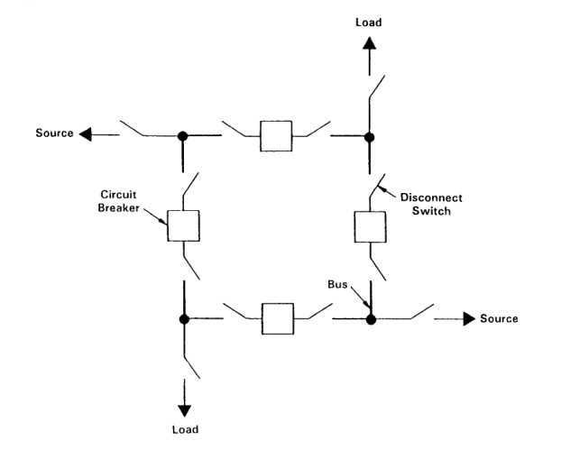
The circuit breakers which serve the faulted position are opened. The failure of a breaker to operate for a line or bus fault will cause two positions to be removed from service.
This configuration allows for any circuit breaker to be removed from service for maintenance without an outage on any circuit.
Line disconnect switches are often installed to allow a line to be removed from service and the ring to remain intact. The two circuit breakers sourcing the line are opened, the line disconnect switch is opened, and then the two circuit breakers are closed.
Ring bus substations are highly reliable and flexible to operate. They are generally limited to a maximum of eight positions to prevent the splitting of the ring. Sources of generation or redundant circuits should not be terminated on adjacent positions of the ring bus. This prevents a failed circuit breaker from removing two sources of generation or two feeds to the same load from service.
Advantages, Disadvantages & Application
Ring bus substations have the advantages of high reliability, flexible operation, and low cost when compared to the breaker and one-half configuration, removal of any breaker from service without circuit outage, and the possibility of expansion to breaker and one-half configuration.
The disadvantages are the complex protective relaying and control and the eight-position limitation.
Application
The ring bus configuration is generally applied in substations from 115 kV through 345 kV, and unlimited application at 500 kV in locations where high system reliability is a requirement.
6. One-Half Breaker Configuration
The one-half breaker configuration is a variation of the ring bus concept on a multiple substation basis. As with the ring bus, two breakers must be tripped to isolate a faulted line or transformer.
In the case of the one-half breaker configuration, one of the breakers is usually at the other end of the transmission line. In the Figure below, Substations A, B, C, D, and E form an extended ring bus.
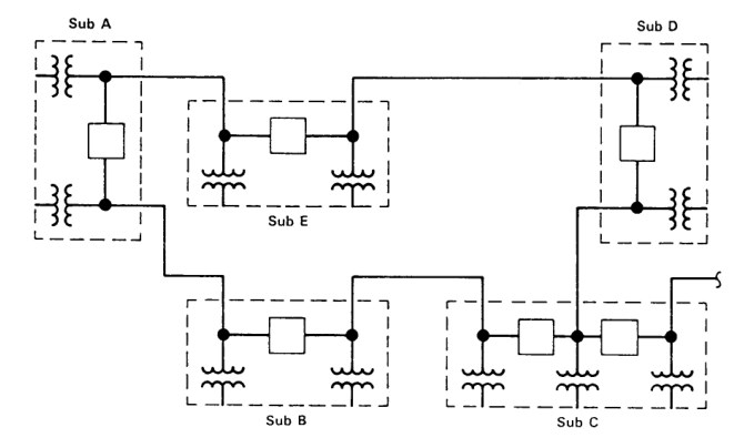
The advantages of this configuration are the same as for the ring bus, and on an individual substation basis, the costs are even lower than for the radial bus.
The one-half breaker configuration is generally applied in substations from 69 kV through 161 kV, and in systems where several substations are located near each other.
7. Breaker and One Half Bus Configuration
The breaker and one-half configuration consist of two main buses. Connected between the main buses are bays which consist of three circuit breakers. A circuit is terminated between each two circuit breakers.
In this configuration, each circuit has a dedicated circuit breaker and shares a circuit breaker with the adjacent circuit, resulting in one and one-half breakers per circuit.
Frequently, a substation is designed to operate initially as a ring bus up through expansion to six positions. Beyond six positions, the substation evolves to a breaker and one-half configuration.
There are two types of the breaker and one-half configurations,
- conventional
- folded.
In the conventional arrangement transmission lines must pass over one of the main buses, causing line termination structures to have higher pull-off points. Also, the installation of line traps, current transformers, and disconnect switches in the lines is difficult.
The folded arrangement locates line termination structures outside the main buses, allowing conventional pull-off heights to be used. The installation of line traps, current transformers, and disconnect switches in the lines are relatively easy. Also, the folded arrangement can be fitted to oddly shaped sites more easily than can the conventional arrangement.
In Breaker and One Half Configuration configuration, only one circuit, the faulted circuit, is removed from service for a fault. The main bus fault does not require that circuits be removed from service.
The failure of a circuit breaker between the main bus and a circuit to operate for the main bus fault requires that only the circuit adjacent to the circuit breaker be removed from service. The failure of a circuit breaker between two circuits to operate for a fault requires the two adjacent circuits to be removed from the service.
This configuration allows any circuit breaker to be removed from service for maintenance without an outage on any circuit.
Line disconnect switches are sometimes installed to allow a circuit to be removed from service and all circuit breakers to remain closed.
Breaker and one-half substations are very reliable and flexible in operation. Sources of generation or redundant circuits should not be connected in the same bay. This prevents a failed breaker from removing two sources of generation or two feeds to the same load from service.
Advantages, Disadvantages & Application
Advantages of breaker and one-half substations over other configurations are
- very high reliability,
- very flexible operation,
- removal of any breaker from service without a circuit outage,
- and ease of expansion, with no limit on the number of bays.
Disadvantages are
- the large land area required,
- the high cost,
- and the complex protective relaying and control.
Application
The breaker and one-half configuration is generally applied in substations from 230 kV through ultrahigh voltages but can be applied at 69 kV, 115 kV,138 kV, and 161 kV.
Because of its high reliability, it is often applied at major generation facilities and at locations where system reliability is critical.
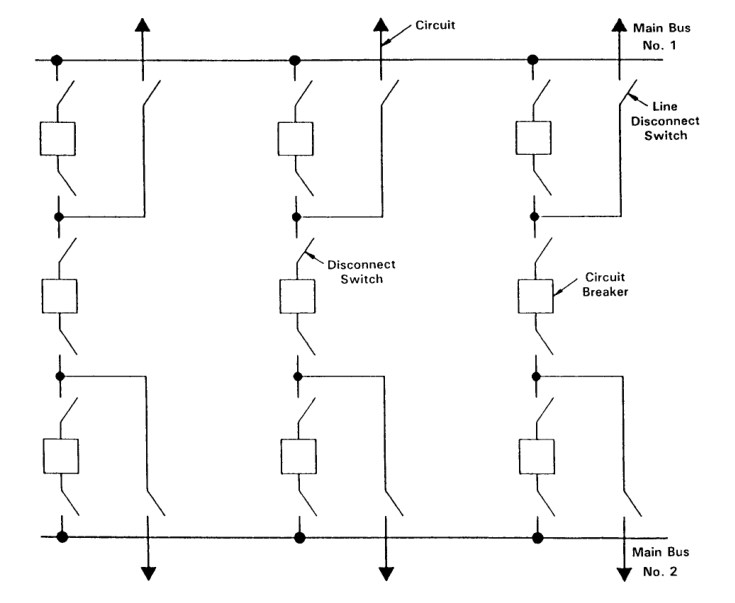
8. Double Breaker Double Bus Configuration
The double breaker double bus configuration consists of two main buses. Connected between the main buses are bays consisting of two circuit breakers, and between the circuit breakers, a circuit. In this configuration, each circuit has two dedicated circuit breakers.
Only the faulted circuit is removed from the service for a fault. A bus fault requires that no circuits be removed from service. The failure of a circuit breaker to operate for a bus fault requires only that the circuit terminated in that bay be removed from service.
This configuration allows any circuit breaker to be removed from service for maintenance without an outage on any circuit. Line disconnect switches are usually not required.
Double breaker double bus substations are the most reliable and are very flexible to operate. They require no separation of sources of generation or redundant circuits.
Advantages, Disadvantages & Application
Double breaker double bus substations have the advantages of
- very high reliability,
- very flexible operation,
- the fact that breaker removal for maintenance will not cause an outage,
- and ease of expansion.
Disadvantages include
- high cost,
- the large land area required,
- and the complex protective relaying and control.
The double breaker double bus configuration is generally applied in substations from 230 kV through ultra-high voltages, nuclear-generating facilities, major generation facilities, and locations where system reliability is very critical.
Comparison of Bus Configuration
The following tabulation compares the relative constructed costs and levels of reliability of each configuration for a substation serving six transmission lines.
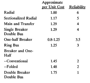
Usually, some bus configurations can be eliminated from consideration for a particular substation on the basis of its function.
A radial bus configuration would not be considered for a nuclear generating station, nor would a double breaker, double bus configuration be considered for a distribution substation.
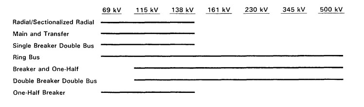
The selection of a bus configuration for a particular substation should always take into account the ultimate anticipated development and function of that installation. The figure above shows at what voltage levels each configuration is typically applied.
Reference: Fundamental Concepts in Substation Design