This is the complete guide to learn electrical engineering basics in 2024.
The study of electrical engineering involves the analysis of the energy transfer from one form to another or from one point to another.
So before beginning the actual study of electrical engineering, it is necessary to discuss the fundamental ideas about the basic elements of electrical engineering like electromotive force, current, resistance, etc.
So if you’re ready to start learning Electrical Engineering Basics, this guide is for you.
Let’s dive right in.
The Structure of Matter
In the understanding of electrical engineering basics, the knowledge of the structure of matter plays an important role.
So, What is Matter?
Everything in the universe is either matter or energy. Matter is everything that we can touch, smell, taste and see. The matter is something that occupies the space. It may be solid, liquid or gaseous.
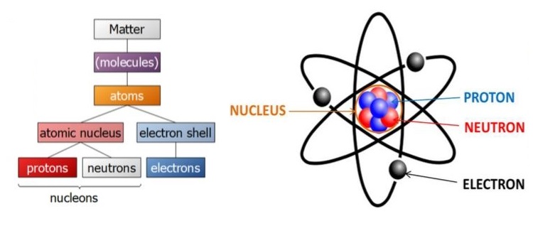
According to the Modern electron theory of matter, all matter whether solid, liquid or gas is composed of very small particles called molecules.
A molecule is, in turn, made up of atoms. An atom consists of a central part called the nucleus.
Around the nucleus, there are a number of electrons revolving in different paths or orbits. The size of the nucleus is very small as compared to the size of the atom. The nucleus contains protons and neutrons.
Structure of Atom
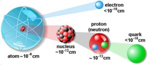
Now the structure of the atom is very clear. An atom is composed of the three fundamental particles, which are invisible to bare eyes. These are the neutron, the proton, and the electron.
- A proton is a positively charged particle. It has a mass 1837 times that of an electron.
- A neutron has the same mass as a proton but no charge. Clearly, the nucleus of an atom bears a positive charge.
- An electron is a negatively charged particle. The negative charge is equal to the positive charge on a proton.
| Fundamental particles of Matter | Symbol | Nature of Charge Possessed | Mass in kg. |
| Neutron | n | Neutral | 1.675 × 10⁻²⁷ |
| Proton | p+ | Positive | 1.675 × 10⁻²⁷ |
| Electron | e– | Negative | 9.107 × 10⁻³¹ |
Under normal conditions, the number of electrons is equal to the number of protons in an atom.
ne = np
Therefore, an atom is neutral as a whole. That means the negative charge on electrons canceling the positive charge on protons.
To conclude the above discussion, it is clear that the matter is electrical in nature.
Electrical Nature of Matter
The matter is electrical in nature means it contains particles of electricity (protons and electrons). Therefore, depending on the number of these particles, we can understand a body exhibits electricity or not.
If the number of protons is equal to the number of electrons in a body, the resultant charge is zero. The body will be electrically neutral.
ne = np (Neutral)
Thus the paper of a book is electrically neutral (i.e. paper exhibits no charge). Because it has the same number of protons and electrons.
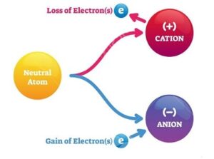
If a neutral body loses some electrons, there occurs a deficit of electrons in the body. So, the body attains a positive charge.
ne < np (Positive)
Hence a positively charged body has a deficit of electrons from the normal due share.
If a neutral body attains some electrons, there occurs an excess of electrons. So, the body attains a negative charge.
ne > np (Negative)
Hence a negatively charged body has an excess of electrons from the normal due share.
Electrons have a very small mass. Thus electrons are much more mobile than protons. On the other hand, protons are powerfully held in the nucleus. Removing or detaching protons from nucleus is impossible.
Electric Charge and Electric Current
Before learning electrical engineering basics, you should understand that electric charge and energy are the two most fundamental quantities in electrical engineering.
Now you will learn about electric charge and current in the next section.
Electric Charge
As we discussed in the structure of the atom, it consists of electrons, protons, and neutrons. Each electron has a negative charge each proton has a positive charge while a neutron has no charge, therefore called neutral.

In an atom, the number of electrons is equal to the number of protons and the atom is electrically neutral. The electrons may be added to or taken away from an atom. This causes the atom to be charged negatively or positively.
- If the atom has a proton in excess of those needed to balance the effect of its electron; called a positive ion.
- If an electron is added to an atom, it attains a negative charge; called a negative ion.
A body having an ionized atom is said to be electrically charged.
Thus total deficiency or addition of excess electrons in an atom is called its charge and the element is said to be charged.
Unit of Charge
The fundamental electric quantity is a charge, and the smallest amount of charge that exists is the charge carried by an electron.
qe = 1.602 × 10⁻¹⁹
The charge possessed by the electron is very very small, hence it is not convenient to take it as the unit of charge.
The unit of the measurement of the charge is Coulomb.
The charge on one electron is 1.602 × 10⁻¹⁹. So the 1-coulomb charge is defined as the charge possessed by the total number of (1/ 1.602 × 10⁻¹⁹) electrons ie. 6.24 × 10¹⁸ number of electrons.
1-coulomb = charge on 6.24 × 10¹⁸ electrons
From the above discussion, it is clear that if an element has a positive charge of one coulomb then that element has a deficiency of 6.24 × 10¹⁸ number of electrons.
Electric Current
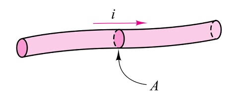
The charge may be at rest or be in motion. A charge in motion constitutes an electric current.
Electric current is defined as the time rate of change of charge passing through a specified area.
Free electrons are responsible for the flow of electric current. To understand this, first, we will see the enlarged view of the inside of a piece of a conductor.
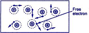
A conductor is one that has abundant free electrons. The free electrons in such a conductor are always moving in random directions as shown in the figure.
The small electrical effort externally applied to such conductor makes all such free electrons to drift along with the metal in a definite particular direction. This direction depends on how the external electrical effort is applied to the conductor.
Such an electrical effort may be an electrical cell, connected across the two ends of a conductor. Such a physical phenomenon is represented in the figure.
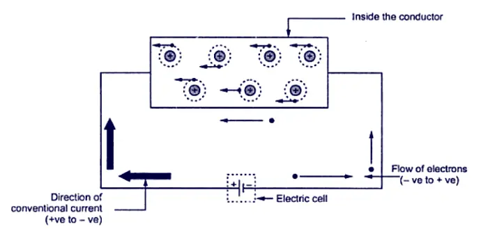
An electrical effort required to drift the free electrons in one particular direction, in a conductor is called Electromotive Force (e.m.f).
The flow of electric current is shown in the figure. The copper strip has a large number of free electrons. For simplicity, only the valence orbits are shown because only the valence electrons can take part in the flow of current.
When electric pressure or voltage is applied, the free electrons being negatively charged start moving towards the positive terminal round the circuit as shown in the figure. This directed flow of electrons is called electric current.
Direction of Current
One common question while learning electrical engineering basics is what is the direction of electric current.
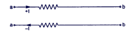
Conventionally, the direction of the electric current is taken along the direction of motion of positive charges. When current is caused by electrons (e.g in metals), the direction of current is opposite to the direction of electron flow.
Thus, when we say that there is a current of 1 A from a point a to point b in a conductor we actually mean that either positive charge is moving from a to b at the rate of 1 C/sec or negative charge is moving from b to a at the rate of 1 C/sec.
Measurement of Current
Another common doubt in electrical engineering basics is how can we measure electric current. Measurement of electric current is explained below.
The flow of charge in a definite direction is called electric current. It is measured by the time rate of flow of charge through the conductor.
If q is the charge flowing through any cross-section of the conductor in time t.
Then, Current, I = q/t
If the rate of flow of charge varies with time, then current at any time (instantaneous current) is given by;
I = dq/dt
where dq is the small charge passing through any cross-section of the conductor in small time dt.
The SI unit of electric current is ampere.
If q = 1 C and t = I s, then I= 1/1 = 1 ampere.
One ampere of current is said to flow through a wire at any section one coulomb of charge flows in one second. If n electrons are passing through any cross-section of the wire in time t. then,
I = q/t = ne/t
where e= —1.6 x 10⁻¹⁹C
Electric Potential and Potential Difference
In this section of electrical engineering basics, you will learn more about electric potential, potential difference, and electromotive force.
Electric Potential
Just as a body raised above the ground has gravitational potential energy, similarly, a charged body has electric potential energy.
When a body is charged, work is done in charging the body. This work done is stored in the body in the form of electric potential energy.
When two similarly charged particles are brought near, they try to repel each other while dissimilar charges attract each other. This means every charged particle has a tendency to do work.
The ability of a charged particle to do the work is called its electric potential.
Mathematically, the electric potential is defined as under:
The electric potential at a point is the electric potential energy per unit charge.
Electric potential, V = Electric potential energy / Charge = W/Q
The SI unit of energy or work is 1 J and that of charge is 1 C so that the SI unit of electric potential is 1 J/ C which is also called 1 volt.
Thus when we say that electric potential at a point is 10 V, it means that if we place a charge of 1 C at that point, the charge will have electric potential energy of 10 J.
Similarly, if we place a charge of 2 C at that point, the charge will have an electric potential energy of 20 J. Note that potential energy per unit charge (i.e electric potential) is 10 V.
Potential Difference
The difference in the potentials of two charged bodies is called potential difference (PD).
Consider two bodies A and B having potentials of +5 V and +3 V respectively as shown in figure 1 below.
Each coulomb of charge on body A has an energy of 5 Joules while each coulomb of charge on body B has an energy of 3 Joules. Clearly, the body A is at a higher potential than body B.
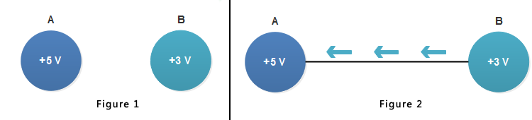
If the two bodies are joined through a conductor [see figure 2 above], then electrons will flow from body B to body A ( The conventional electric current will be in opposite direction i.e. from A to B).
When the two bodies attain the same potential, the flow of current stops. Therefore, we arrive at a very important conclusion that current will flow in a circuit if the potential difference exists.
No potential difference, no current flow. It may be noted that the potential difference is sometimes called voltage.
Unit of Potential Difference
Since the unit of electric potential is volt, one can expect that the unit of potential difference will also be volt. It is defined as :
The potential difference between two points is 1 Volt if one joule of work is done in transferring 1C of charge from the point of lower potential to the point of higher potential.

Consider points A and B in an electrical circuit as shown in the figure above. Suppose VA = VB = 1 Volt. It means that 1 J of work will be done in transferring 1C of charge from point B to point A.
Alternatively, 1 J of work (or energy) will be released (as heat) if 1 C of charge moves from point A to point B. Note that volt is the unit of energy.
Concept of EMF and Potential Difference
There is a distinct difference between e.m.f. and potential difference.
The e.m.f. of a device, say a battery, is a measure of the energy the battery gives to each coulomb of charge. Thus if a battery supplies 4 joules of energy per coulomb, we say that it has an e.m.f. of 4 volts. The energy given to each coulomb in a battery is due to the chemical action.
The potential difference between two points says A and B, is a measure of the energy used by one coulomb in moving from A to B.
Thus if the potential difference between points A and B is 2 volts, it means that each coulomb will give up the energy of 2 joules in moving from A to B.
We have now laid the groundwork and covered most of the electrical engineering basics till now. Let’s move further and understand some basic laws in electrical engineering.
Basic Electrical Engineering Laws
Laws are very important to understand the electrical engineering basics. The importand basic electrical engineering laws are
- Ohm’s Law
- Kirchoff’s Law
Ohm’s Law
The next important topic in electrical engineering basics is Ohms Law. Ohm’s Law is a fundamental law in Electrical Engineering. This a magical law that solves most of the problems in electrical engineering.
The relationship between the voltage across a conductor and current through a conductor was first discovered by German scientist George Simon Ohm. This relationship is called Ohm’s law.
Ohms law is stated as the current (I) flowing through a conductor is directly proportional to the potential difference (V) across its ends provided the physical conditions (temperature, strain, etc.) do not change.
I α V
V/I = constant = R
where R is a constant of proportionality and is called resistance of the conductor.
For example, if in the figure, the potential difference between points A and B of the conductor is V and current flowing is I, then V/I will be constant and equal to R, the resistance of the conductor between points A and B.
If V is doubled up, current will also be doubled up so that ratio V is constant.

If a graph is drawn between the applied potential difference (V) and current (I) flowing through the conductor, it will be a straight line passing through the origin.
Note the slope of the graph gives the resistance of the conductor (tan θ = V/I = R).
Resistance, Resistivity & Conductance
In this section of basic electrical engineering, you will learn fundamental electrical quantities such as resistance, resistivity, conductance, and conductivity. In addition to it, you will learn their units and calculation.
Resistance
The resistance of a conductor is defined as the ratio of the potential difference applied across its ends to the resulting current through the conductor i.e
R = V/I
Resistance is an opposition to the flow of current.
If the resistance of the circuit is doubled, the current is reduced to one half. If the resistance is tripled, the current is reduced to one-third and so on.
Unit of Resistance
The SI unit of potential difference is Volt and that of current is Ampere.
Therefore, the SI unit of resistance is V/A which has been given a special name ohm (symbol Ω)
1 ohm = 1 Ω = 1 V/A
A conductor is said to have a resistance of 1 ohm if a potential difference of 1 V across its ends causes a current of 1 A to flow through it.
Use of resistance
Resistance can be very useful when we have to control the flow of current. For example, consider the circuit shown in the figure. A component called rheostat has been added to the motor circuit.

A rheostat is an adjustable resistor. The current flow must overcome the resistance of the circuit. As the rheostat is adjusted for more resistance, the circuit current/decreases and the motor slows down. As the rheostat is adjusted for less resistance, the circuit current increases and the motor speeds up.
Thus we see that resistance can be used to control the speed of the motor.
Resistances can be combined in different methods. They are used to dim lights, control loudness, and perform many other useful circuit functions.
Calculating Resistance
The resistance R of the material of length l and area of cross-section A is:
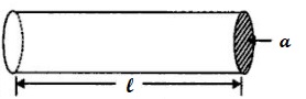
R = ρl/A
where ρ (Greek letter ‘Rho’) is the resistivity or specific resistance of the material.
l is the length of the material.
A is the area of the material.
Unlike resistance, the value of resistivity or specific resistance depends upon the nature of the material and temperature.
Resistivity or Specific Resistance
R = ρl/A
If l=1m, A=1m2, the R=ρ
Hence specific resistance (or resistivity) of a material is the resistance offered by 1 m length of wire material having an area of cross-section of 1m2.
The SI unit of resistivity is ohm-m (Ωm).
Different materials have different resistivities.
For example, the resistivity of copper is 1.7 x 10⁻⁸ Ωm. It means that if you take a copper wire 1 m long and has an area of cross-section of 1m2, then the resistance of this piece of copper wire will be 1.7 x 10⁻⁸ Ω.
Conductance
Conductance (G) is the reciprocal of resistance. If a conductor has a resistance R, then its conductance G is given by :
G = 1/R
A circuit with high conductance has low resistance, and a circuit with low conductance has high resistance.
The SI unit of conductance is Siemen. The symbol of Siemen is S.
Suppose a wire has a resistance of 0.5 Ω. Then its conductance is G = 1/R = 1/0.5 = 2S
Conductivity
The reciprocal of resistivity of a conductor is called its conductivity. The symbol conductivity is σ (sigma).
If a conductor has resistivity ρ, then its conductivity is:
σ = 1/ρ
Now, G = 1/R = A/ρl
G = σ A/l
Clearly, the SI unit of conductivity is Siemens per meter (Sm-1).
Electric Power
The power of an electric appliance is the rate at which electrical energy is convened into other forms of energy (e.g. heat. etc.).
For example, a 60 W bulb converts 60J of electrical energy into heat and light each second.
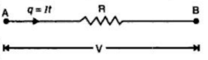
Thus referring to the figure, as the charge q (= It), moves from point A to B, it loses electric potential energy = qV. In other words, qV joules of electrical energy is converted into heat in t seconds.
∴ Electric Power = qV/t =(It)V/t = VI J/s or watts
Electrical Power = VI watts
= I2R watts
= V2/R watts
Anyone of the three formulas can be used to calculate electric power, depending upon the problem in hand.
Unit of Electric Power
P =VI
The SI unit of p.d. is 1 V and that of current is 1 A so that SI unit of power =1V x 1A=1 VA or 1 watt ( 1 W).
Hence electric power of a circuit or device is one watt if a current of 1 A flows through it when a p.d. of 1 V is maintained across it.
The bigger units of electric power are kilowatt (kW) and megawatt (MW).
1 kW is 1000 W ; 1MW = 103 kW = 106 W.
Note. Electric appliances are rated in terms of electric power. The faster the appliance converts electrical energy into some other form of energy, the greater the electric power it has. Thus, in 1 second, a 100 W bulb converts more electrical energy into heat and light than a 60 W bulb.
Electrical Energy
The electrical energy consumed in a circuit is the loss of electrical potential energy in maintaining current in the circuit.
Thus in the figure above, as the charge q (= It) moves from point A to B, it loses electric potential energy = q V = V/ t joules. This loss of electric potential energy is convened into heat.
We say that electrical energy consumed in t seconds is VIt joules.
∴ Electrical energy consumed, W = VIt = I2Rt = (V2/R)t Joules
Unit of Electrical Energy
W = VIt = Power x Time
The SI unit of power is Watt and that of time is Second.
So, that SI unit of electrical energy =1W x 1s = 1 Watt- second (Ws) or 1 Joule.
1 J (or 1Ws ) energy is consumed when a device (e.g., bulb. heater, etc.) converts electrical energy to other forms at a rate of 1 W for a time of 1 second.
Commercial Unit of Electrical Energy
In practice, we measure electrical energy in kilowatt-hour (kWh).
1 kWh energy is consumed when a device converts electrical energy to other forms at a rate of 1 kW for a time of 1 hour.
Electrical energy in kWh = Power in kW x Time in hours
The electricity bills are made on the basis of total electrical energy consumed by the consumer. The unit for billing of electrical energy is 1 kWh. Thus when we say that a consumer has consumed 100 units, it means that electrical energy consumption is 100 kWh.
Power And Energy Formulas
It has already been discussed that electric power, as well as electrical energy consumed, can be expressed by three formulas.
While using these formulas, the following points may be kept in mind :
Electric Power, P = I2R = V2/R watts
The electrical energy consumed, W = I2Rt = (V2/R)t joules
The above formulas apply only to resistors and to devices (e.g., electric bulb, heater, electric kettle, etc.) where all electrical energy consumed is converted into heat.
Electric power, P = VI watts
The electrical energy consumed, W = VIt joules
Similarly, these two formulas apply to any type of load including the one mentioned above.
Electrical Materials
We have covered most about electrical engineering basics that would clear the fundamentals of electrical engineering. These are essential topics for a beginner in electrical engineering.
Another important topic in electrical engineering basics is Electrical Materials. The materials used in electrical and electronics engineering can be broadly divided into three major types.
- Conductors
- Semiconductors
- Insulators
Conductors (e.g copper, aluminium, etc.) conduct current very easily while insulators (e.g. glass, mica, paper) practically conduct no current.
In other words, conductors have small resistivity and insulators have a high value of resistivity.
The resistivity of semiconductors (e.g. germanium, silicon, etc.) lies between conductors and insulators.
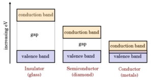
Read more about band diagram conductors, semiconductors, and insulators.
Conductors
Conductors are formed by metallic bonds. These bonds are based on a structure of positive metal ions surrounded by a cloud of electrons.
Conductors have a positive temperature coefficient of resistance ie their resistance increases with the rise in temperature and vice-versa.
The application of conductors is to carry current in electric circuits.
Semiconductors
Semiconductors are formed by covalent bonds.
They have a negative temperature coefficient of resistance i.e their resistance decreases with the rise in temperature and vice-versa.
Application of semiconductors is in the manufacturing of electronic devices (e.g crystal diodes, transistors, etc .)
Insulators
Insulators are predominantly covalent compounds. The valence electrons are tightly locked with neighboring atoms and are not available to support the flow of current.
Insulators have a negative temperature coefficient of resistance i.e. their resistance decreases with the rise in temperature and vice-versa.
The application of insulators is to confine the current to the desired path.
Frequently Asked Questions in Electrical Engineering Basics
In this section, we will discuss some of the most frequently asked questions in Electrical Engineering Basics. This will help you to understand and clear the concepts discussed in the previous sections of this article.
Why does a positive charge attract a negative charge?
It is the tendency of every body to have minimum electric potential i.e., to obtain zero potential. A positive charge means deficit of electrons while the negative charge indicates excess of electrons. Consequently, positive and negative charges attract each other to have minimum electric potential.
A wire is carrying current. Is it charged?
No. The current in a wire is due to the drifting of free electrons in a definite direction. But the number of electrons in the wire at any instant is equal to the number of protons. Hence, the net charge on the wire is zero.
The thermal speeds of free electrons are very large. Inspite of these high speeds, why they fail to escape from the surface of a conductor?
The free electrons in a conductor are free only to the extent that they may transfer from one atom to another within the conductor.
It is because the free electrons that start at the surface of a conductor find behind them the positive ions pulling them back and none pulling forward. Thus at the surface of a conductor, a free electron encounters forces that prevent it to leave the conductor surface. To escape the conductor surface free electrons use external energy.