In this article, you’ll learn about electrical components that oppose the flow of AC by temporarily storing energy as electric fields. These devices are called capacitors, and their action is known as capacitance.
This article discusses capacitors and capacitance. By the end of this article, you will learn the following.
- What is capacitor and capacitance and how a practical capacitor work?
- What are the different units of capacitance?
- What are the different types of capacitors?
- Series and parallel capacitors and their connection
- Advantages and disadvantages of fixed and variable capacitors
We all know that, electrical components can oppose the flow of alternating current in three ways.
- Resistance
- Inductance
- Capacitance
Resistance slows the flow of ac or dc charge carriers (usually electrons) by brute force. Inductance restricts the flow of ac charge carriers by temporarily storing the energy as a magnetic field.
Capacitance, about which you’ll learn in this article, impedes the flow of ac charge carriers by temporarily storing the energy as an electric field.
What is Capacitance?
Imagine two huge, flat sheets of metal that are excellent electrical conductors. Suppose each of the metal plates is of the shape of a huge rectangular football stadium and are placed one over the other, separated by only 1 foot of space.
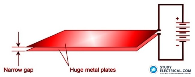
If these two sheets of metal are connected to the terminals of a battery, they will become charged electrically, one positively and the other negatively.
If the plates were small, they would both become charged almost instantly, attaining a relative voltage equal to the voltage of the battery. But because the plates are gigantic, it will take a little time for the negative plate to reach full negative potential, and an equal time for the other plate to reach full positive potential.
Eventually, the voltage between the two plates will equal the battery voltage, and an electric field will exist in the space between the plates. This electric field will be small at first because the plates don’t charge up right away.
But the charge will increase over a period of time, depending on how large the plates are, and also depending on how far apart they are.
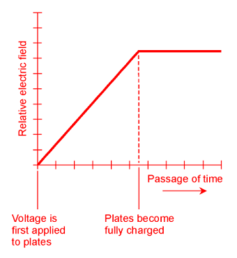
The figure above is a relative graph showing the intensity of the electric field between the plates as a function of time, elapsed from the instant the plates are connected to the battery terminals.
Energy will be stored in this electric field. The ability of the plates, and of the space between them, to store this energy is the property of capacitance.
As a quantity or variable, capacitance is denoted by the uppercase italic letter C.
Practical Capacitor
It’s out of the question to make a practical capacitor of the preceding dimensions.
But two sheets, or strips, of foil, can be placed one on top of the other, separated by a thin, nonconducting sheet such as paper, and then the whole assembly can be rolled up to get a large effective surface area. When this is done, the electric flux becomes great enough so that the device exhibits significant capacitance.
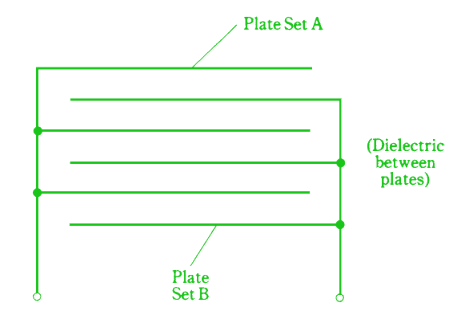
Alternatively, two sets of several plates each can be meshed together with air in between them, and the resulting capacitance is significant at high ac frequencies.
In a capacitor, the electric flux concentration is multiplied when a dielectric of a certain type is placed between the plates. This increases the effective surface area of the plates so that a physically small component can be made to have a large capacitance.
The voltage that a capacitor can handle depends on
- the thickness of the metal sheets or strips,
- the spacing between them,
- and the type of dielectric used.
In general, capacitance is directly proportional to the surface area of the conducting plates or sheets.
Capacitance is inversely proportional to the separation between conducting sheets. In other words, the closer the sheets are to each other, the greater the capacitance.
The capacitance also depends on the dielectric constant of the material between the plates.
A vacuum has a dielectric constant of 1; some substances have dielectric constants that multiply the effective capacitance many times.
The Unit of Capacitance
When a battery is connected between the plates of a capacitor, the potential difference between the plates builds up at a rate that depends on the capacitance. The greater the capacitance, the slower the rate of change of voltage in the plates.
The unit of capacitance is an expression of the ratio between the current that flows and the rate of voltage change between the plates as the plates become charged.
A capacitance of 1 farad (1 F) represents a current flow of 1 A while there is a voltage increase of 1 V/s. A capacitance of 1 F also results in 1 V of potential difference for an electric charge of 1 C.
A farad is a huge unit of capacitance. You’ll almost never see a capacitor with a value of 1 F.
Commonly employed units of capacitance are the microfarad (µF) and the picofarad (pF).
- 1 µF represents 0.000001 (10−6 ) F
- 1 pF is a millionth of a microfarad or 0.000000000001 (10−12 ) F
Physically small components can be made to have fairly large capacitance values. Conversely, some capacitors with small values take up large physical volumes.
The physical size of a capacitor, if all other factors are held constant, is proportional to the voltage that it can handle. The higher the rated voltage, the bigger the component.
Connection of Capacitor in a Circuit
A capacitor can be connected in a circuit in two forms.
- Series
- Parallel
The value of capacitance changes when we connect the capacitors in these two forms. Let’s learn how to calculate equivalent capacitance in both circuits.
Capacitors in Series
With capacitors, there is rarely any mutual interaction. This makes capacitors easier to work with than inductors. We don’t have to worry about mutual capacitance very often, the way we have to be concerned about mutual inductance when working with wire coils.
Capacitors in series add together like resistors or inductors in parallel.
Suppose you have several capacitors with values C1, C2, C3,. . . , Cn connected in series.
You can find the reciprocal of the total capacitance, 1/C, using the following formula:
1/C = 1/C1 + 1/C2 + 1/C3 + . . . + 1/Cn
The net capacitance of the series combination, C, is found by taking the reciprocal of the number you get for 1/C.
If two or more capacitors are connected in series, and one of them has a value that is tiny compared with the values of all the others, the net capacitance is roughly equal to the smallest capacitance.
Capacitors in Parallel
Capacitors in parallel add like resistances in series. The total capacitance is the sum of the individual component values.
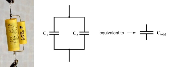
The net capacitance of the parallel combination is,
C = C1 + C2 + C3 + . . . + Cn
If two or more capacitors are connected in parallel, and one of the capacitances is far larger than any of the others, the total capacitance can be taken as approximately the value of the biggest one.
Different Types of Capacitors
The capacitors are broadly divided into two types.
- Fixed Capacitors
- Variable Capacitors
Read more: Different Types of Capacitors
Fixed Capacitors
A fixed capacitor has a value that cannot be adjusted, and that (ideally) does not vary when environmental or circuit conditions change.
The following are some of the common types of fixed capacitors.
- Paper Capacitor
- Mica Capacitor
- Ceramic Capacitor
- Plastic-Film Capacitors
- Electrolytic Capacitors
- Tantalum Capacitors
- Semiconductor Capacitors
Related: Application of different types of fixed capacitors
Dielectric Materials in Fixed Capacitors
Just as certain solids can be placed within a coil to increase the inductance, materials exist that can be sandwiched in between the plates of a capacitor to increase the capacitance.
The substance between the plates is called the dielectric of the capacitor.
Air is an efficient dielectric; it has almost no loss. But it is difficult to get very much capacitance using air as the dielectric.
Some kind of solid material is usually employed as the dielectric for most fixed capacitors. Dielectric materials accommodate electric fields well, but they are poor conductors of electric currents. In fact, dielectric materials are known as good insulators.
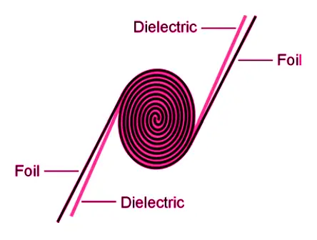
Solid dielectrics increase the capacitance for a given surface area and spacing of the plates. Solid dielectrics also allow the plates to be rolled up, squashed, and placed very close together. This geometry acts to maximize the capacitance per unit volume.
1. Paper Capacitors
In the early days of electronics, capacitors were commonly made by placing paper, soaked with mineral oil, between two strips of foil. Then rolling the assembly up, attaching wire leads to the two pieces of foil, and enclosing the rolled-up foil and paper in an airtight cylindrical case.
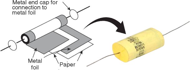
Paper capacitors can still sometimes be found in older electronic equipment.
They have values ranging from about 0.001 µF to 0.1 µF.
These capacitors can handle low to moderate voltages, usually up to about 1000 V.
2. Mica Capacitors
Mica is a naturally occurring, solid, transparent mineral substance that flakes off in thin sheets. It makes an excellent dielectric for capacitors.
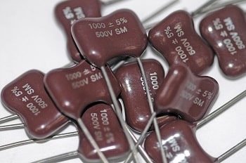
Mica capacitors can be manufactured by alternately stacking metal sheets and layers of mica, or by applying silver ink to sheets of mica. The metal sheets are wired together into two meshed sets, forming the two terminals of the capacitor. This scheme is shown in the figure.
Mica capacitors have low loss, and are therefore highly efficient, provided their voltage rating is not exceeded.
Voltage ratings can be up to several thousand volts if thick sheets of mica are used. But mica capacitors are large physically in proportion to their capacitance.
The main application for mica capacitors is in radio receivers and transmitters.
Their capacitances are a little lower than those of paper capacitors, ranging from a few tens of picofarads up to about 0.05 µF.
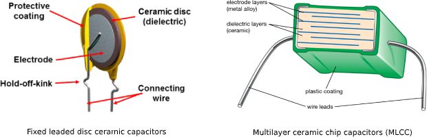
3. Ceramic Capacitors
Ceramic materials work well as dielectrics. Sheets of metal are stacked alternately with wafers of ceramic to make these capacitors. The meshing/layering geometry is used. Ceramic, like mica, has low loss and allows for high efficiency.
For small values of capacitance, only one layer of ceramic is needed, and two metal plates can be glued to the disk-shaped material, one on each side. This type of component is known as a disk ceramic capacitor.
Alternatively, a tube or cylinder of ceramic can be employed, and metal ink applied to the inside and outside of the tube. Such units are called tubular capacitors.
Ceramic capacitors have values ranging from a few picofarads to about 0.5 µF.
Their voltage ratings are comparable to those of paper capacitors.
4. Plastic-Film Capacitors
Plastics make good dielectrics for the manufacture of capacitors. Polyethylene and polystyrene are commonly used.
The method of manufacture is similar to that for paper capacitors. Stacking methods can be used if the plastic is rigid. The geometries can vary, and these capacitors are therefore found in various shapes.
Capacitance values for plastic-film units range from about 50 pF to several tens of microfarads.
Most often they are in the range of 0.001 µF to 10 µF.
Plastic capacitors are employed at audio frequency (AF) and radio frequency (RF), and at low to moderate voltages.
The efficiency is good, although not as high as that for mica dielectric or air-dielectric units.
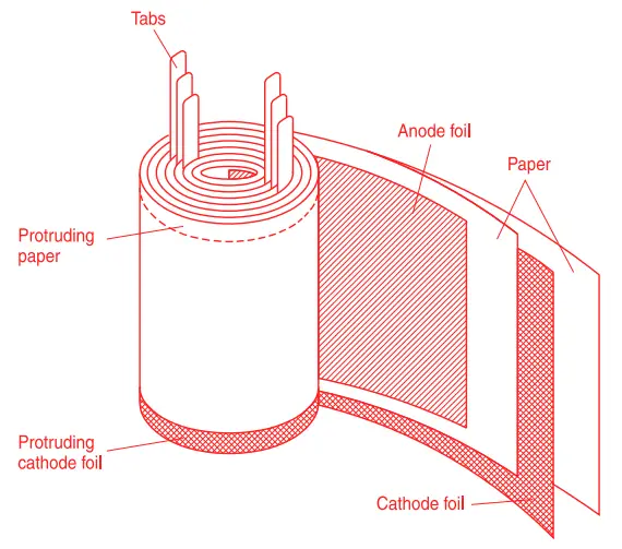
5. Electrolytic Capacitors
All of the aforementioned types of capacitors provide relatively small values of capacitance. They are also nonpolarized, meaning that they can be hooked up in a circuit in either direction.
An electrolytic capacitor provides greater capacitance than any of the preceding types, but it must be connected in the proper direction in a circuit to work right. An electrolytic capacitor is a polarized component.
Electrolytic capacitors are made by rolling up aluminum foil strips, separated by paper saturated with an electrolyte liquid. The electrolyte is a conducting solution.
When dc flows through the component, the aluminum oxidizes because of the electrolyte. The oxide layer is nonconducting and forms the dielectric for the capacitor. The layer is extremely thin, and this results in a high capacitance per unit volume.
Electrolytic capacitors can have values up to thousands of microfarads, and some can handle thousands of volts.
These capacitors are most often seen in AF circuits and in dc power supplies.
6. Tantalum Capacitors
Another type of electrolytic capacitor uses tantalum rather than aluminum.
The tantalum can be a foil, as is the aluminum in a conventional electrolytic capacitor. It can also take the form of a porous pellet, the irregular surface of which provides a large area in a small volume. An extremely thin oxide layer forms on the tantalum.
Tantalum capacitors have high reliability and excellent efficiency.
They are often used in military applications because they almost never fail.
They can be used in AF and digital circuits in place of aluminum electrolytic.
7. Semiconductor Capacitors
Semiconductor materials can be employed to make capacitors. A semiconductor diode conducts current in one direction and refuses to conduct in the other direction.
When a voltage source is connected across a diode so that it does not conduct, the diode acts as a capacitor. The capacitance varies depending on how much of this reverse voltage is applied to the diode.
The greater the reverse voltage, the smaller the capacitance. This makes the diode act as a variable capacitor. Some diodes are specially manufactured to serve this function. Their capacitances fluctuate rapidly along with pulsating dc. They are called varactor diodes or simply varactors.
Capacitors can be formed in the semiconductor materials of an integrated circuit (also called an IC or chip) in much the same way. Sometimes, IC diodes are fabricated to serve as varactors.
Another way to make a capacitor in an IC is to sandwich an oxide layer into the semiconductor material, between two layers that conduct well.
Most ICs look like little boxes with protruding metal prongs. The prongs provide the electrical connections to external circuits and systems.
Semiconductor capacitors usually have small values of capacitance.
They are physically tiny and can handle only low voltages.
The advantages are miniaturization and ability, in the case of the varactor, to change in value at a rapid rate.
Variable Capacitors
The capacitance of a component can be varied at will by adjusting the mutual surface area between the plates, or by changing the spacing between the plates.
The two most common types of variable capacitors (besides varactors) are the air variable and the trimmer. You will also sometimes encounter coaxial capacitors.
Here you will learn the following three variable capacitors
- Air Variable Capacitor
- Trimmer Capacitor
- Coaxial Capacitor
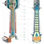
1. Air Variable Capacitor
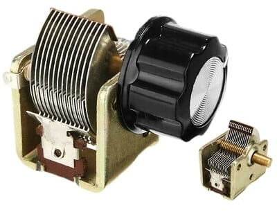
By connecting two sets of metal plates so that they mesh, and by affixing one set to a rotatable shaft, a variable capacitor is made.
The rotatable set of plates is called the rotor, and the fixed set is called the stator.
This is the type of component you might have seen in older radio receivers, used to tune the frequency. Such capacitors are still used in transmitter output tuning networks.
The figure below is a functional drawing of an air-variable capacitor.
Air variables have a maximum capacitance that depends on the number of plates in each set, and also on the spacing between the plates.
Common maximum values are 50 to 500 pF; minimum values are a few picofarads.
The voltage-handling capability depends on the spacing between the plates. Some air variables can handle many kilovolts.
Air variables are used primarily in RF applications.
They are highly efficient, and are nonpolarized, although the rotor is usually connected to common ground (the chassis or circuit board).
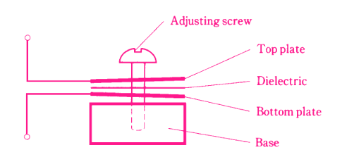
2. Trimmer Capacitors
When it is not necessary to change the value of a capacitor very often, a trimmer can be used.
It consists of two plates, mounted on a ceramic base and separated by a sheet of plastic, mica, or some other solid dielectric. The plates are flexible and can be squashed together more or less by means of a screw.
Sometimes two sets of several plates are interleaved to increase the capacitance.
Trimmers can be connected in parallel with an air variable so that the range of the air variable can be adjusted. Some air-variable capacitors have trimmers built-in.
Typical maximum values for trimmers range from a few picofarads up to about 200 pF. They handle low to moderate voltages, are highly efficient, and are nonpolarized.
3. Coaxial Capacitors
You know that sections of transmission lines can work as inductors. They can act as capacitors, too.
If a section of the transmission line is less than 1 ⁄ 4 wavelength long and is left open at the far end (rather than shorted out), it behaves as a capacitor. The capacitance increases with length.
The most common transmission-line capacitor uses two telescoping sections of metal tubing. This is called a coaxial capacitor.
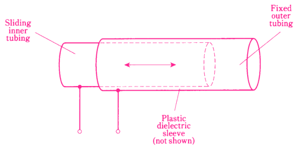
It works because there is a certain effective surface area between the inner and the outer tubing sections. A sleeve of the plastic dielectric is placed between the sections of tubing.
This allows the capacitance to be adjusted by sliding the inner section in or out of the outer section.
Coaxial capacitors are used in RF applications, particularly in antenna systems.
Their values are generally from a few picofarads up to about 100 pF.
Capacitor Specifications
When you are looking for a capacitor for a particular application, it’s important to find a component that has the right specifications for the job.
Here are two of the most important specifications to watch for before selecting a capacitor:
Tolerance
Capacitors are rated according to how nearly their values can be expected to match the rated capacitance. The most common tolerance is ±10%; some capacitors are rated at ±5% or even at ±1%.
The lower (or tighter) the tolerance number, the more closely you can expect the actual component value to match the rated value.
For example, a ±10% capacitor rated at 100 pF can range from 90 to 110 pF. But if the tolerance is ±1%, the manufacturer guarantees that the capacitance will be between 99 and 101 pF.
Example
A capacitor is rated at 0.10 µF ± 10%. What is its guaranteed range of capacitance?
First, multiply 0.10 by 10 percent to get the plus-or-minus variation. This is 0.10 × 0.10 = 0.010 µF. Then add and subtract this from the rated value to get the maximum and minimum possible capacitances. The result is a range of 0.09 to 0.11 µF.
Temperature Coefficient
Some capacitors increase in value as the temperature increases. These components have a positive temperature coefficient.
Some capacitors decrease in value as the temperature rises; these have a negative temperature coefficient.
Some capacitors are manufactured so that their values remain constant over a certain temperature range. Within this span of temperatures, such capacitors have zero temperature coefficient.
The temperature coefficient is specified in percent per degree Celsius (%/°C).
Sometimes, a capacitor with a negative temperature coefficient can be connected in series or parallel with a capacitor having a positive temperature coefficient, and the two opposite effects cancel out over a range of temperatures.
In other instances, a capacitor with a positive or negative temperature coefficient can be used to cancel out the effect of temperature on other components in a circuit, such as inductors and resistors.