- Belted cables — upto 11 kV
- Screened cables — from 22 kV to 66 kV
- Pressure cables — beyond 66 kV.
Belted Cables

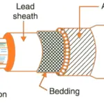
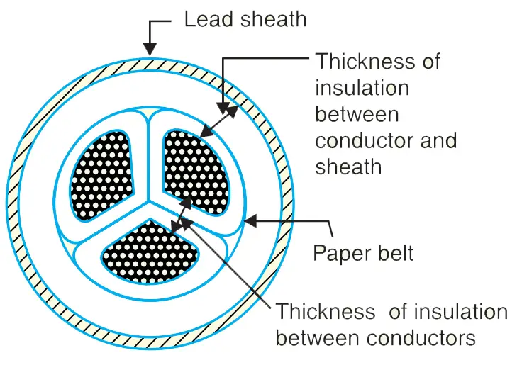
The cores are insulated from each other by layers of impregnated paper.
Another layer of impregnated paper tape, called paper belt is wound round the grouped insulated cores.
The gap between the insulated cores is filled with fibrous insulating material (jute etc.) so as to give circular cross-section to the cable.
The belt is covered with lead sheath to protect the cable against ingress of moisture and mechanical injury. The lead sheath is covered with one or more layers of armoring with an outer serving (not shown in the figure).
Application of Belted Cables
However, for high voltages (beyond 22 kV), the tangential stresses also become important. These stresses act along the layers of paper insulation.
The leakage current causes local heating, resulting in the risk of breakdown of insulation at any moment. In order to overcome this difficulty, screened cables are used where leakage currents are conducted to earth through metallic screens.
Screened Cables
- H type cables
- S.L. type cables.
1. H type cables
The cores are laid in such a way that metallic screens make contact with one another. An additional conducting belt (copper woven fabric tape) is wrapped round the three cores.
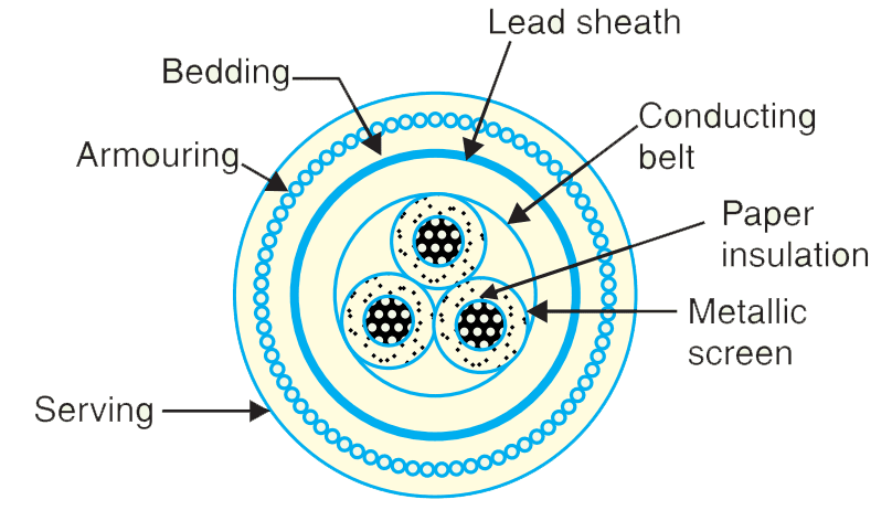 The cable has no insulating belt but lead sheath, bedding, armouring and serving follow as usual.
 It is easy to see that each core screen is in electrical contact with the conducting belt and the lead sheath.
Advantages of H-type Cables
Firstly, the perforations in the metallic screens assist in the complete impregnation of the cable with the compound and thus the possibility of air pockets or voids (vacuous spaces) in the dielectric is eliminated.
The voids if present tend to reduce the breakdown strength of the cable and may cause considerable damage to the paper insulation.
Secondly, the metallic screens increase the heat dissipating power of the cable.
2. S.L. type cables
There is no overall lead sheath but only armouring and serving are provided.

The S.L. type cables have two main advantages over H-type cables.
- Firstly, the separate sheaths minimise the possibility of core-to-core breakdown.
- Secondly, bending of cables becomes easy due to the elimination of overall lead sheath.
However, the disadvantage is that the three lead sheaths of S.L. cable are much thinner than the single sheath of H-cable and, therefore, call for greater care in manufacture.
Pressure Cables
When the operating voltages are greater than 66 kV, pressure cables are used.
In such cables, voids are eliminated by increasing the pressure of the compound and for this reason, they are called pressure cables.
- Oil-filled cables
- Gas pressure cables
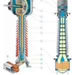
1. Oil-filled cables
As a result, the oil under pressure (it is the same oil used for impregnation) is kept constantly supplied to the channel by means of external reservoirs placed at suitable distances (say 500 m) along the route of the cable.
Types of Oil Filled Cables
- Single-core conductor channel,
- Single-core sheath channel and
- Three-core filler-space channels.
i. Single-core conductor channel
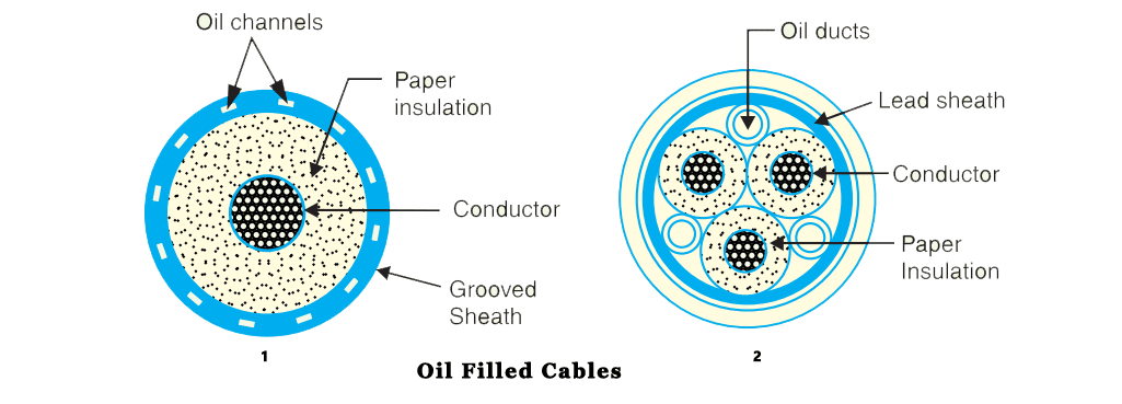
The figure shows the constructional details of a single-core conductor channel, oil filled cable.

The oil channel is formed at the centre by stranding the conductor wire around a hollow cylindrical steel spiral tape.
The oil under pressure is supplied to the channel by means of external reservoir.
As the channel is made of spiral steel tape, it allows the oil to percolate between copper strands to the wrapped insulation. The oil pressure compresses the layers of paper insulation and prevents the possibility of void formation.
However, when the cable temperature falls during light load conditions, the oil from the reservoir flows to the channel.
ii. Single-core sheath channel
In this type of cable, the conductor is solid similar to that of solid cable and is paper insulated. However, oil ducts are provided in the metallic sheath as shown.
In the 3-core oil-filler cable shown in figure, the oil ducts are located in the filler spaces. These channels are composed of perforated metal-ribbon tubing and are at earth potential.
- Firstly, formation of voids and ionization are avoided.
- Secondly, allowable temperature range and dielectric strength are increased.
- Thirdly, if there is leakage, the defect in the lead sheath is at once indicated and the possibility of earth faults is decreased.
However, their major disadvantages are the high initial cost and complicated system of laying.
Gas pressure cables
Principle of gas pressure cables
At the same time, the increased pressure produces radial compression which tends to close any voids. This is the underlying principle of gas pressure cables.
Construction of Gas Pressure Cables

The sheath is protected by
The gas pressure produces radial compression and closes the voids that may have formed between the layers of paper insulation.
Moreover, maintenance cost is small and the nitrogen gas helps in quenching any flame. However, it has the disadvantage that the overall cost is very high.