This is a continuation of the previous article (Introduction to PLC Ladder Programming) in PLC Programming series. Please go through an introduction to Ladder Programming before reading this post.
In this post, we will discuss about what is a ladder diagram and how to draw a ladder diagram.
Ladder Diagram
How to Draw a Ladder Diagram?
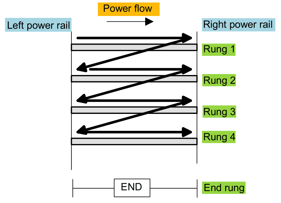
The vertical lines of the diagram represent the power rails between which circuits are connected. The power flow is taken to be from the left-hand vertical across a rung.
Each rung on the ladder defines one operation in the control process.
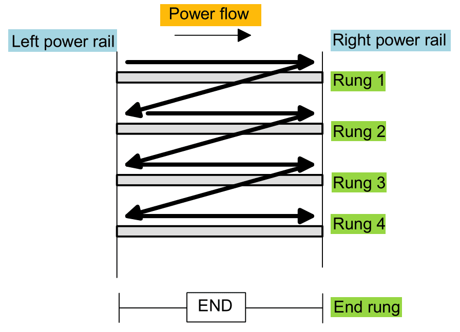
A ladder diagram is read from left to right and from top to bottom. The figure shows the scanning motion employed by the PLC. The top rung is read from left to right.
Then the second rung down is read from left to right and so on. When the PLC is in its run mode, it goes through the entire ladder program to the end, the end rung of the program is clearly denoted, and then promptly resumes at the start. This procedure of going through all the rungs of the program is termed a cycle. The end rung might be indicated by a block with the word END or RET for return since the program promptly returns to its beginning.
Each rung must start with an input or inputs and must end with at least one output. The term input is used for control action, such as closing the contacts of a switch, used as an input to the PLC. The term output is used for a device connected to the output of a PLC, e.g. a motor.
Electrical devices are shown in their normal condition. Thus a switch which is normally open until some object closes it is shown as open on the ladder diagram. A switch that is normally closed is shown closed.
A particular device can appear in more than one rung of a ladder. For example, we might have a relay which switches on one or more devices. The same letters and/or numbers are used to label the device in each situation.
The inputs and outputs are all identified by their addresses, the notation used depending on the PLC manufacturer. This is the address of the input or output in the memory of the PL.