A servomotor is also defined as a rotary actuator that allows for very fine control of angular positions. This article explains controlling a servo motor with Arduino in detail.
Many servos are widely available and quite cheap. Servos can drive a great amount of current. This means that you wouldn’t be able to use more than one or two on your Arduino board without using an external source of power.
When do we need Servos?
Whenever we need a way to control a position related to a rotation angle, we can use servos.
Servos can not only be used to move small parts and make objects rotate but can also be used to move the object including them. Robots work in this fashion, and there are many Arduino-related robot projects on the Web that are very interesting.
In the case of robots, the servo device case is fixed to a part of an arm, for instance, and the other part of the arm is fixed to the rotating part of the servo.
How to control servos with Arduino
There is a nice library that should be used at first, named Servo.
This library supports up to 12 motors on most Arduino boards and 48 on the Arduino Mega.
By using other Arduino boards over Mega, we can figure out some software limitations. For instance, pins 9 and 10 cannot be used for PWM’s analogWrite() method (http://arduino.cc/en/Reference/analogWrite).
Servos are provided in three-pin packages:
- 5 V
- Ground
- Pulse; that is, control pin
Basically, the power supply can be easily provided by an external battery, and the pulse still remains the Arduino board.
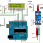
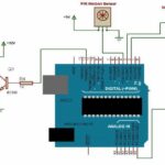
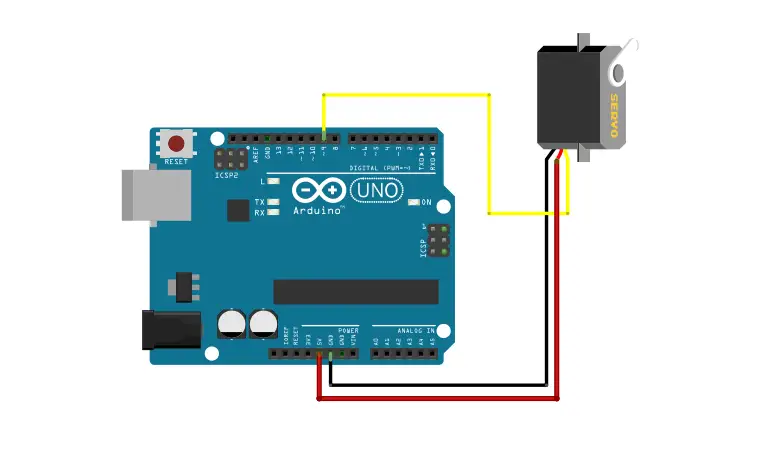
Wiring Servo to Arduino

A servo motor has 3 output wires. The red and brown wires are connected to the Vcc and Ground respectively.
The yellow pin is the signal pin. It is connected to one of the PWM inputs of the Arduino.
- Servo red wire – 5V pin Arduino
- Servo brown wire – Ground pin Arduino
- Servo yellow wire – PWM pin Arduino
Firmware for controlling one servo using the Servo library
Here is a firmware that provides a cyclic movement from 0 degrees to 180 degrees.
#include
Servo myServo; // instantiate the Servo object
int angle = 0; // store the current angle void setup()
{
// pin 9 to Servo object myServo
myServo.attach(9);
}
void loop()
{
for(angle = 0; angle < 180; angle += 1)
{
myServo.write(angle);
delay(20);
}
for(angle = 180; angle >= 1; angle -=1)
{
myServo.write(angle);
delay(20);
}
}
We first include the Servo library header. Then we instantiate a Servo object instance named myServo.
In the setup() block, we have to make something special. We attach pin 9 to the myServo object. This explicitly defines the pin as the control pin for the Servo instance myServo.
In the loop() block, we have two for() loops, and it looks like the previous example with the piezoelectric device. We define a cycle, progressively incrementing the angle variable from 0 to 180 and then decrementing it from 180 to 0, and each time we pause for 20 ms.
There is also a function not used here that I want to mention, Servo.read(). This function reads the current angle of the servo (that is, the value passed to the last-call to write()). This can be useful if we are making some dynamic stuff without storing it at each turn.