In this article, we are going to study the basics of low voltage circuit breaker design and construction. The operation and arc extinction of different types of circuit breakers were already discussed. The basic design principles of low rating circuit breakers (MCB, MCCB, GFCI, etc.) are explained here. Variations to these design principles will be discussed later.
- Frame
- Contacts
- Arc Chute Assembly
- Operating Mechanism
- Trip Unit
The functions and features of each component are explained with pictures.
1. Frame
The frame provides an insulated housing to mount the circuit breaker components. The construction material is usually a thermal set plastic, such as glass-polymer. The construction material can be a factor in determining the interruption rating of the circuit breaker.
Typical frame ratings include maximum voltage, maximum ampere rating, and interrupting rating.
2. Contacts
The current flowing in a circuit controlled by a circuit breaker flows through the circuit breaker’s contacts. When a circuit breaker is turned off or is tripped by a fault current, the circuit breaker interrupts the flow of current by separating its contacts.
- Straight-Through Contacts
- Blow-Apart Contacts
Straight-Through Contacts
Some circuit breakers use a straight-through contact arrangement, so-called because the current flowing in one contact arm continues in a straight line through the other contact arm.

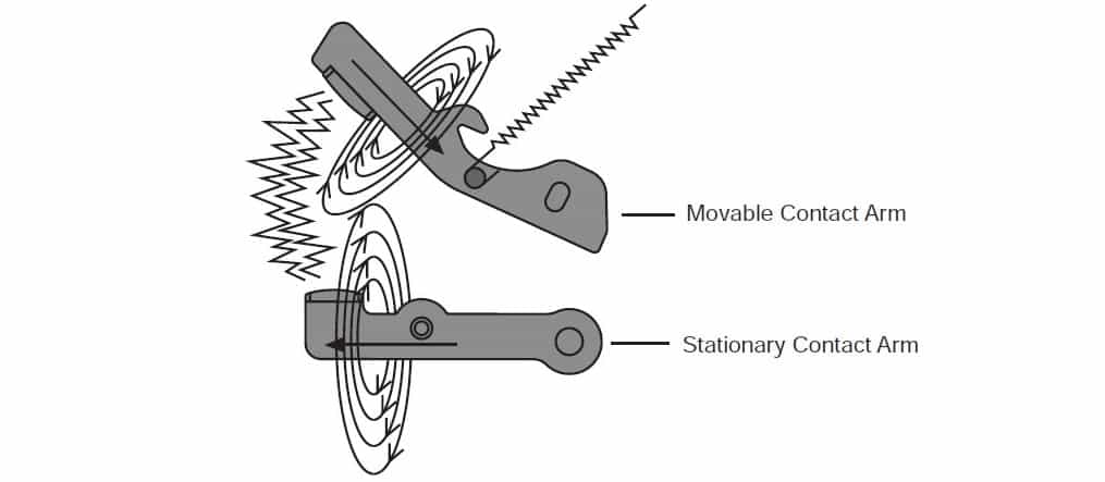
Blow-Apart Contacts
As current flows through the contact arms, magnetic fields develop around each arm. Because the current flow in one arm is opposite in direction to the current flow in the other arm, the two magnetic fields oppose each other.
3. Arc Chute Assembly
The arc is extinguished in this assembly. The current flowing in a circuit controlled by a circuit breaker flows through the circuit breaker’s contacts.
When a circuit breaker is turned off or is tripped by a fault current, the circuit breaker interrupts the flow of current by separating its contacts.
This assembly is made up of several “U” shaped steel plates that surround the contacts. As the arc developes, it is drawn into the arc chute where it is divided into smaller arcs, which are extinguished faster.

- First, arcing can damage the contacts.
- Second, the arc ionizes gases inside the molded case.
Arcing phenomenon and methods of arc extinction were discussed in previous articles.
Operating Handle
A circuit breaker must provide a manual means for energizing and de-energizing a circuit and must be capable of being reset after a fault condition has been cleared.
These capabilities are typically provided through the use of an operating handle.

4. Operating Mechanism
The operating handle is connected to the moveable contact arm through an operating mechanism.
In the following illustration, the operating handle is moved from the “OFF” to the “ON” position (Figure 1). In this process, a spring begins to apply tension to the mechanism.
When the handle is directly over the center, the tension in the spring is strong enough to snap the contacts closed. This means that the speed of the contact closing is independent of how fast the handle is operated.

The contacts are opened by moving the operating handle from the “ON” to the “OFF” position (Figure 2). In this process, spring begins to apply tension to the mechanism.
When the handle is directly over the center, the tension in the spring is strong enough to snap the contacts open. Therefore, contact opening speed is also independent of how fast the handle is operated.
5. Trip Unit