
The machine which produces 3 phase power from mechanical power is called an alternator or synchronous generator. The working of an alternator is based on the principle that when the flux linking a conductor changes, an emf is induced in the conductor.
Alternators are the primary source of all the electrical energy we consume. These machines are the largest energy converters found in the world. They convert mechanical energy into AC energy.
Working Principle of Alternator
An alternator operates on the same fundamental principle of electromagnetic induction as a DC generator. The working of an alternator is based on the principle that when the flux linking a conductor changes, an emf is induced in the conductor.
Like a DC generator, an alternator also has an armature winding and a field winding. But there is one important difference between the two.
In a DC generator, the armature winding is placed on the rotor in order to provide a way of converting alternating voltage generated in the winding to a direct voltage at the terminals through the use of a rotating commutator.
The field poles are placed on the stationary part of the machine. Since no commutator is required in an alternator, it is usually more convenient and advantageous to place the field winding on the rotating part (i.e., rotor) and armature winding on the stationary part (i.e., stator).
An alternator has 3,-phase winding on the stator and a DC field winding on the rotor. This DC source (called exciter) is generally a small DC shunt or compound generator mounted on the shaft of the alternator.
Rotor construction is of two types, namely;
- Salient (or projecting) pole type
- Non-salient (or cylindrical) pole type
In salient pole type alternator, salient or projecting poles are mounted on a large circular steel frame which is fixed to the shaft of the alternator.
In cylindrical pole type alternator, the rotor is made of a smooth solid forged-steel radial cylinder having a number of slots along the outer periphery.
Alternator Operation
The rotor winding is energized from the DC exciter and alternate N and S poles are developed on the rotor.
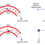
When the rotor is rotated in the anti-clockwise direction by a prime mover, the stator or armature conductors are cut by the magnetic flux of rotor poles. Consequently, EMF is induced in the armature conductors due to electromagnetic induction.
The induced e.m.f. is alternating since N and S poles of rotor alternately pass the armature conductors. The direction of induced e.m.f. can be found by Fleming right-hand rule and frequency is given by;
f = PN / 120
where N = speed of the rotor in r.p.m.
P = number of rotor poles
The magnitude of the voltage induced in each phase depends upon the rotor flux, the number and position of the conductors in the phase and the speed of the rotor.
When the rotor is rotated, a 3-phase voltage is induced in the armature winding. The magnitude of induced e.m.f. depends upon the speed of rotation and the DC exciting current. The magnitude of e.m.f. in each phase of the armature winding is the same. However, they differ in phase by 120° electrical.
Video Animation
Watch the working of Alternator by learnengineering.org in this video.


Supper
Nice explanation
good your explanation alterneter
Glad to be one of the visitors on this awe inspiring internet site :D.
Given more information than books. Better explanation.
I am afraid many are wrong with them saying AC power flows in a electrical conductor, ie copper wires.
There is No current flows at all at any time to say different means you have no understanding of the principle of a simple alternator.