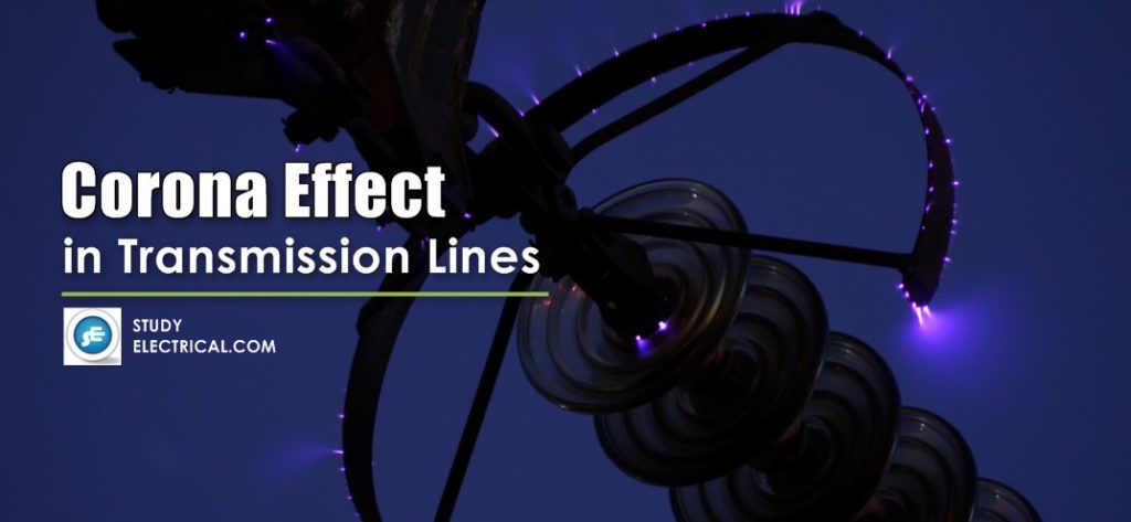

What is Corona?
The phenomenon of violet glow, hissing noise and production of ozone gas in an overhead transmission line is known as the corona.
In this article, we will study what is corona, how the corona is formed in transmission lines, the advantages & disadvantages of corona and how can we reduce the corona effect.
When an alternating potential difference is applied across two conductors whose spacing is large as compared to their diameters, there is no apparent change in the condition of atmospheric air surrounding the wires if the applied voltage is low.
However, when the applied voltage exceeds a certain value, called critical disruptive voltage, the conductors are surrounded by a faint violet glow called corona.
The phenomenon of the corona is accompanied by a hissing sound, production of ozone, power loss and radio interference.
Interference with communication circuits may be due to both electromagnetic and electrostatic action, the former producing currents, which are superposed on the true speech currents, thereby setting up the distortion and the latter raising the potential of the communication circuit as a whole.
The higher the voltage is raised, the larger and higher the luminous envelope becomes, and greater are the sound, the power loss, and the radio noise. If the applied voltage is increased to breakdown value, a flash-over will occur between the conductors due to the breakdown of air insulation.
If the conductors are polished and smooth, the corona glow will be uniform throughout the length of the conductors, otherwise, the rough points will appear brighter.
With DC voltage, there is a difference in the appearance of the two wires. The positive wire has a uniform glow about it, while the negative conductor has a spotty glow.
How Corona is Formed?
Some ionization is always present in the air due to cosmic rays, ultraviolet radiations, and radioactivity.
Therefore, under normal conditions, the air around the conductors contains some ionized particles (i.e., free electrons and +ve ions) and neutral molecules.
When a potential difference is applied between the conductors, a potential gradient is set up in the air which will have a maximum value at the conductor surfaces.
Under the influence of the potential gradient, the existing free electrons acquire greater velocities. The greater the applied voltage, the greater the potential gradient and more is the velocity of free electrons.
When the potential gradient at the conductor surface reaches about 30 kV per cm (max. value), the velocity acquired by the free electrons is sufficient to strike a neutral molecule with enough force to dislodge one or more electrons from it.
This produces another ion and one or more free electrons, which in turn are accelerated until they collide with other neutral molecules, thus producing other ions. Thus, the process of ionization is cumulative.
The result of this ionization is that either corona is formed or spark takes place between the conductors.
Corona Loss
The ions produced by the electric field result in space charges which move around the conductor. The energy required for the charges to remain in motion is derived from the supply system. The space surrounding the conductor is lossy.
In order to maintain the flow of energy over the conductor in the field wherein this additional energy would have been otherwise absent, it is necessary to supply this additional loss from the supply system. This additional power is referred to as corona loss.
An empirical relation was deducted after conducting various experiments and studying the effects of various parameters on corona loss. According to it, Corona loss is,
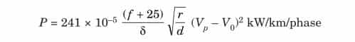
where,
f is the frequency of supply,
δ the air density correction factor,
Vp the operating voltage in kV and
V0 the critical disruptive voltage.
The equation derived is for a fair-weather condition.
The approximate loss under foul weather condition is obtained by taking V0 as 0.8 times the fair-weather value.
As a matter of fact, with perfectly smooth and cylindrical conductors no corona loss occurs until a visual critical voltage is reached when the loss suddenly takes a definite value as calculated by the above formula. It then follows the quadratic law for higher voltages.
The empirical relation shown above has certain limitations and gives correct results only if the supply frequency lies between 25 to 120 Hz, the conductor radius is greater than 0.25 cm and the ratio Vp/V0 > 1.8.
Also, a small error in m0, the irregularity factor, will lead to wrong results when using this formula.
Factors Affecting Corona Loss
The following are the factors that affect corona loss on overhead transmission lines:
- Electrical factors
- Frequency and waveform of the supply
- Magnetic Field around the Conductor
- Atmospheric factors
- Pressure and Temperature Effect
- Dust, Rain, Snow and Hail Effect
- Factors connected with the conductors.
- The diameter of the Conductor
- Number of Conductors/Phases
- Profile of the Conductor
- Surface Conditions of the Conductors
- Heating of the Conductor by Load Current
The factors are discussed one by one in the sequence.
1. Electrical Factors
- Frequency and waveform of the supply
- Corona loss is a function of frequency. Thus higher the frequency of supply the higher are corona losses. This shows that DC corona loss is less as compared with AC corona.
- Actually, because of the corona phenomenon in case of AC, third harmonics are always present and hence the frequency is not only 50 Hz but it contains 3rd harmonic component also. Hence the corona loss is still large as compared with 50 Hz alone.
- Magnetic Field around the Conductor
- The field around the conductor in addition to being a function of the voltage, depends upon the configuration of the conductors, i.e., whether they are placed in the vertical configuration, delta formation, etc.
- Say if the formation is horizontal the field near the middle conductor is large as compared to the outer conductors i.e., the critical disruptive voltage is lower for the middle conductors and hence the corona loss on the middle conductor is more as compared with the two outer conductors.
- The height of the conductors from the ground has its effect on corona loss. The smaller the height, the greater the corona loss.
- When lines are irregularly spaced, the surface gradients of the conductors and hence the corona losses if any are unequal.
2. Atmospheric Factors
- Pressure and Temperature Effect
- From the expression for loss, it is clear that it is a function of air density correction factor δ which appears directly in the denominator of the expression and indirectly in the value of critical disruptive voltage.
- The lower the value of δ the higher the loss; because the loss is α(V – V0)2, the lower the value of δ, the lower the value of V0 and hence higher the value of (V – V0)2, where V is the operating voltage in kV.
- This shows that the effect of δ on corona loss is very serious. For lower values, the pressure should be low and temperature higher. It is for this reason that the corona loss is more on hilly areas than on plain areas.
- Dust, Rain, Snow and Hail Effect
- The particles of dust clog to the conductor; thereby the critical voltage for local corona reduces which increases corona loss.
- Similarly, the bad atmospheric conditions such as rains, snow, and hailstorm reduce the critical disruptive voltage and hence increase the corona loss.
3. Factors Connected with Conductor
- The diameter of the Conductor
- From the expression for corona loss, it can be seen that the conductor size appears at two places and if other things are assumed constant,
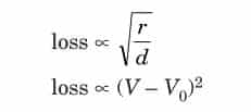
- It appears from the first relation that loss is proportional to the square root of the size of the conductor, i.e., larger the dia of the conductor larger will be the loss.
- But from the second expression as V0 is approximately directly proportional to the size of the conductor, hence larger the size of the conductor larger will be the critical disruptive voltage and hence smaller will be the factor (V – V0)2.
- It is found in practice that the effect of the second proportionality is much more than the first on the corona losses, and hence larger the size of the conductor lower is the corona loss.
- Number of Conductors/Phases
- For operating voltage 380 kV and above it is found that one conductor per phase gives large corona loss and hence large radio interference (RI) level which interferes with the communication lines which normally run parallel to the power lines.
- This problem of large corona loss is solved by using two or more than two conductors per phase which are known as bundling of conductors.
- By bundling the conductors the self GMD of the conductors is increased thereby; the critical disruptive voltage is increased and hence corona loss is reduced.
- Profile of the Conductor
- By this is meant the shape of the conductor whether cylindrical, flat, oval, etc. Because of field uniformity in case of the cylindrical conductor the corona loss is less in this as compared to any other shape.
- Surface Conditions of the Conductors
- The conductors are exposed to atmospheric conditions. The surface would have dirt etc. deposited on it which will lower the disruptive voltage and increase corona loss.
- Heating of the Conductor by Load Current
- The heating of the conductor by the load current has an indirect reducing effect on the corona loss. Without such heating, the conductor would tend to have a slightly lower temperature than the surrounding air.
- In the absence of heating, dew in the form of tiny water drops would form on the conductor in foggy weather or at times of high humidity, which induces additional corona.
- The heating effect of the load current is, however, large enough to prevent such condensation.
- During rains, the heating of the conductor has no influence on the corona loss but, after the rain, it accelerates the drying of the conductor surface. The time during which the water drops remain on the surface is reduced and the loss is also reduced.
- For long transmission lines which pass through routes of varying altitudes, the average value of corona loss is obtained by finding out the corona loss per km at a number of points and then an average is taken out.
Advantages and Disadvantages of Corona
Corona is a phenomenon where the localized electric field near an energized conductor can be sufficiently concentrated to produce an electric discharge that can ionize air (causing it to become conductive), create plasma and produce ozone.
This electrical discharge can also cause small amounts of sound and radio interference (“radio noise”). Discharges and noise also result in unfavorable power losses. While this phenomenon is generally associated with voltages above 200 kV, sufficient conductor diameter/surface area (especially through the use of multiple “bundled” conductors in each phase) can provide the appropriate level of mitigation.
Corona has many advantages and disadvantages. In the correct design of a high voltage overhead line, a balance should be struck between the advantages and disadvantages.
Advantages of Corona
- Due to corona formation, the air surrounding the conductor becomes conducting and hence virtual diameter of the conductor is increased. The increased diameter reduces the electrostatic stresses between the conductors.
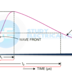
- Corona reduces the effects of transients produced by surges.
Disadvantages of Corona
- Corona is accompanied by a loss of energy. This affects the transmission efficiency of the line.
- Ozone is produced by corona and may cause corrosion of the conductor due to chemical action.
- The current drawn by the line due to corona is non-sinusoidal and hence non-sinusoidal voltage drop occurs in the line. This may cause inductive interference with neighboring communication lines.
Audio Noise
When corona is present on the conductors, EHV lines generate audible noise, which is especially high during polluted weather. The noise is broadband, which extends from very low frequency to about 20 kHz.
Corona discharges generate positive & negative ions, which are alternately attracted & repelled by the periodic reversal of polarity of the a.c excitations. Their movement gives rise to sound-pressure waves at frequencies of twice the power frequency and its multiples, in addition to the broadband spectrum which is the result of random motions of the ions.
Audible noise can become a serious problem from ‘psychoacoustics ‘ point of view, leading to insanity due to loss of sleep at night to inhabitants residing close to an EHV line.
Radio Interference (RI)
Pulse-type corona discharge from transmission line conductors gives rise to interference to the radio broadcast in the range of 0.5 MHz to1.6 MHz.
Electromagnetic Effect
The emf induced in the communication circuit due to neighboring power circuit depends on its distance with respect to the power line.
The net emf induced due to electromagnetic coupling with a 3-phase line is small since the phasor sum of induced EMFs tends to zero.
However, the presence of certain harmonics would cause seriously high induced EMFs. This problem is more serious these days since the power line current is not sinusoidal because of he use of static controllers.
Electrostatic Effect
The communication line may acquire dangerously high potential due to electrostatically induced charges. The interference between power & communication lines can be reduced considerably by transposing the conductors of both power & communication lines.
The communication line may require electrostatic shielding to overcome electrostatic interference.
How to Reduce Corona Effect
It has been seen that intense corona effects are observed at a working voltage of 33 kV or above. Therefore, the careful design should be made to avoid corona on the sub-stations or bus-bars rated for 33 kV and higher voltages.
The corona effects can be reduced by the following methods :
- By increasing conductor size.
- By increasing conductor spacing.
- By using Bundled Conductors.
1. By increasing conductor size.
By increasing conductor size, the voltage at which corona occurs is raised and hence corona effects are considerably reduced.
This is one of the reasons that ACSR conductors which have a larger cross-sectional area are used in transmission lines.
2. By increasing conductor spacing.
By increasing the spacing between conductors, the voltage at which corona occurs is raised and hence corona effects can be eliminated.
However, spacing cannot be increased too much otherwise the cost of supporting structure (e.g., bigger cross arms and supports) may increase to a considerable extent.
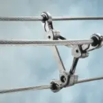
3. Bundled conductors

They are employed to reduce corona loss and radio interference (shown in the figure above).
They increase the cross-sectional area of transmission lines and reduces the voltage gradient in the vicinity of the line. Thus reduces the possibility of the corona discharge.