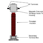
Current Transformers (CT’s) are instrument transformers that are used to supply a reduced value of current to meters, protective relays, and other instruments.
Current Transformers provide isolation from the high voltage primary, permit grounding of the secondary for safety, and step-down the magnitude of the measured current to a value that can be safely handled by the instruments.
Current transformers can be divided into two major types,
- Single-turn (bar) primary and
- Multi-turn wound primary.
Single Turn (Bar) Primary CT
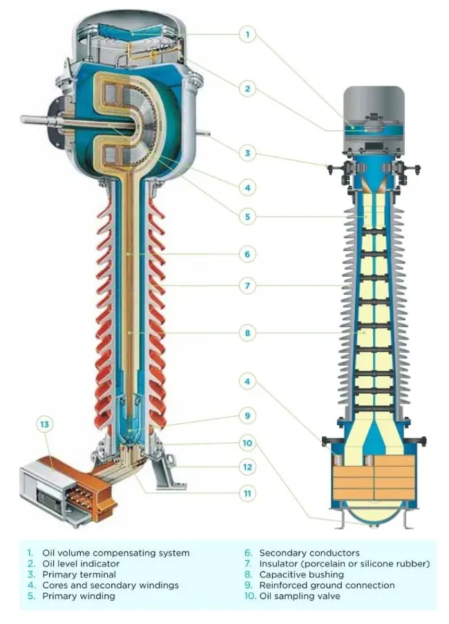
In the single turn primary current transformer, primary conductor may form part of the current transformer assembly, in which case it must be suitably insulated to withstand the system voltage to earth where it passes through the c.t. core and secondary windings.
The majority of single-turn primary current transformers make use of an insulated conductor provided as part of other equipment such as bushings of switchgear or power transformers, and the current transformer is merely a ring core with a toroidally wound secondary winding.
Multi Turn Wound Primary CT
In Multi-turn Wound Primary current Transformer, the primary winding is also constructed inside the current transformer body.
The primary winding is usually of a single turn. Wound Primary Current transformers are used in applications which require small current transformation ratios. They are more accurate and have a higher burden capacity. The wound primary is usually designed with toroidal cores for high efficiency.
Wound primary current transformers may have the primary and secondary windings arranged concentrically, the secondary winding invariably being the inner winding since it is advantageous to keep the resistance of this winding as low as possible, or, in designs intended primarily for operating instruments, meters and simple overcurrent relays, the primary and secondary windings may be disposed on different limbs of the core.
Such an arrangement results in minimum weights of windings, and the flux leakage effect resulting from this loose coupling reduces the phase error and limits the secondary current produced by high primary overcurrents.