
By parallel operation of single-phase transformers, we mean two or more transformers are connected to the same supply bus bars on the primary side and to a common bus bar/load on the secondary side. Such a requirement is frequently encountered in practice.
Two transformers A and B connected in parallel are shown in the figure.

While connecting two or more than two transformers in parallel, it is essential that their terminals of similar polarities are joined to the same busbars as shown.
The wrong connections may result in a dead short-circuit and primary transformers may be damaged unless protected by fuses or circuit breakers.
Need of Parallel Operation in Single Phase Transformers
- Firstly, if one transformer fails, the continuity of supply can be maintained through other transformers.
- Secondly, when the load on the substation becomes more than the capacity of the existing transformers, another transformer can be added in parallel.
- Thirdly, any transformer can be taken out of the circuit for repair/routine maintenance without interrupting the supply to the consumers.
- Non-availability of a single large transformer to meet the total load requirement.
- The power demand might have increased over time necessitating augmentation of the capacity. More transformers connected in parallel will then be pressed into service.
- To ensure improved reliability. Even if one of the transformers gets into a fault or is taken out for maintenance/repair the load can be continued to be serviced.
- To reduce spare capacity. If many smaller size transformers are used one machine can be used as spare. If only one large machine is feeding the load, a spare of similar rating has to be available. The problem of spares becomes more acute with fewer machines in service at a location.
- When transportation problems limit the installation of large transformers at a site, it may be easier to transport smaller ones to the site and work them in parallel.
Conditions for Parallel Operation of Single Phase Transformer
- Transformers should be properly connected with regard to their polarities.
- The voltage ratings and voltage ratios of the transformers should be the same.
- The per unit or percentage impedances of the transformers should be equal.
- The reactance/resistance ratios of the transformers should be the same.
1. Connection with regard to Polarity
The first condition for successful parallel operation of single phase transformer is that the transformers should be properly connected with regard to their polarities.
This condition is absolutely essential because wrong connections may result in dead short-circuit.
Figure (i) shows the correct method of connecting two single-phase transformers in parallel.

Figure (ii) shows the wrong method of connecting two single-phase transformers in parallel. Here the two secondaries are so connected that their e.m.f.s EA and EB are additive.
This may lead to short-circuiting conditions and a very large circulating current will flow in the loop formed by the two secondaries.
Such a condition may damage the transformers unless they are protected by fuses and circuit breakers.
2. Same Voltage Rating and Voltage Ratio
The next condition for parallel operation of single phase transformer is the same voltage rating and voltage ratio.
This condition is desirable for the satisfactory parallel operation of transformers.
If this condition is not met, the secondary e.m.f.s will not be equal and there will be circulating current in the loop formed by the secondaries. This will result in the unsatisfactory parallel operation of transformers.
Let us illustrate this point. Consider two single-phase transformer A and B operating in parallel as shown in the figure.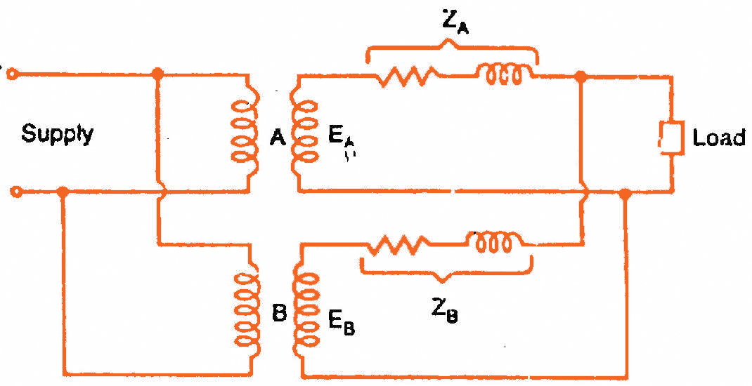
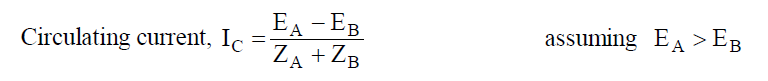
Even a small difference in the induced secondary voltages can cause a large circulating current in the secondary loop because impedances of the transformers are small. This secondary circulating current will cause current to be drawn from the supply by the primary of each transformer.
These currents will cause copper losses in both primary and secondary. This creates heating with no useful output.
When the load is connected to the system, this circulating current will tend to produce unequal loading conditions i.e., the transformers will not share the load according to their kVA ratings. It is because the circulating current will tend to make the terminal voltages of the same value for both transformers.
Therefore, the transformer with a smaller voltage ratio will tend to carry more than its proper share of the load.
Thus, one transformer would tend to become overloaded than the other and the system could not be loaded to the summation of transformer ratings without overloading one transformer.
3. Equal Percentage Impedance
Another condition for parallel operation of single phase transformer is all transformers should have equal percentage impedance.
This condition is also desirable for proper parallel operation of single-phase transformers.
If this condition is not met, the transformers will not share the load according to their kVA ratings.
Sometimes this condition is not fulfilled by the design of the transformers.
In that case, it can be corrected by inserting proper amount of resistance or reactance or both in series with either primary or secondary circuits of the transformers where the impedance is below the value required to fulfill this condition.
4. Same Reactance/Resistance Ratio
If the reactance/resistance ratios of the two transformers are not equal, the power factor of the load supplied by the transformers will not be equal.
In other words, one transformer will be operating with a higher and the other with a lower power factor than that of the load.
Equal Percentage Impedance (Condition 3) is much more important than Same Reactance/Resistance Ratio (condition 4).
Considerable deviation from Same Reactance/Resistance Ratio (condition 4) will result in only a small reduction in the satisfactory degree of operation.
When desired, condition (4) also may be improved by inserting external impedance of proper value.